
Telescoping-type front fork bicycle suspensions

a technology of front fork and suspension system, which is applied in the direction of friction roller based transmission, steering device, cycle equipment, etc., can solve the problems of design that must operate at relatively high stress, close to the strength limits of materials being used, and critical weight and stiffness

Inactive Publication Date: 2004-12-14
VOSS DARRELL W +1
View PDF28 Cites 32 Cited by
  • Summary
  • Abstract
  • Description
  • Claims
  • Application Information

AI Technical Summary

Problems solved by technology

In the design of competition bicycles and bicycle parts, weight and stiffness are critical issues.
This results in a design that must operate at relatively high stresses, close to the strength limits of the materials being used.
There are numerous bicycle suspension forks currently on the market that are not very weight efficient.
They have been designed for basic suspension function, without adequate consideration for weight optimization or steering and braking control.
These designs tend to be relatively heavy and their stiffness to weight and strength to weight ratios are not very high.
They are also relatively flexible laterally and in torsion and cannot provide the stability and accurate steering and braking control for the front wheel assembly that is desired for serious competition cycling.
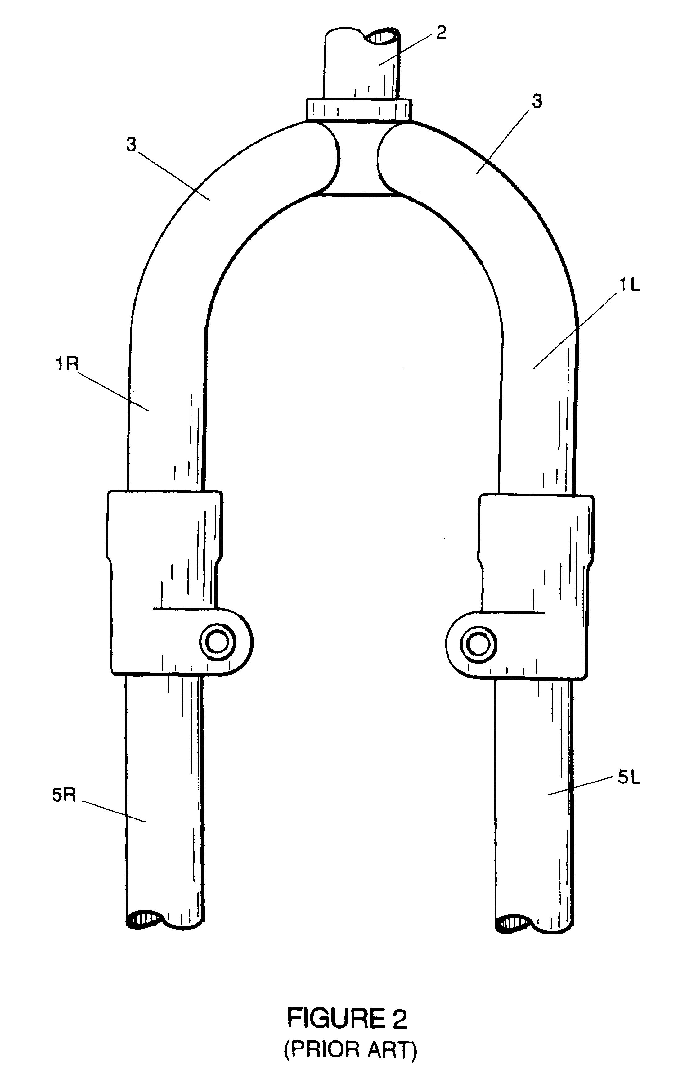
Most of the prior art fork suspensions use brake arch designs that are inherently too flexible to control wheel wobble and braking action.

Method used


Image

  • Telescoping-type front fork bicycle suspensions
  • Telescoping-type front fork bicycle suspensions
  • Telescoping-type front fork bicycle suspensions

Examples


embodiment b (

FIG. 6b) illustrates an end fitting design using adhesive bonding. Both the stanchion socket (6-10) and the bridge (6-9) are designed for bonding. This option has the advantage of lightness and improved fatigue strength but it does not provide an easy means for disassembly.

embodiment c (fig.6c)

Embodiment C (FIG. 6c) uses a collet assembly CA to make the connection. The collet assembly has an inner taper (6-11), internal threads IT, a sliding compression wedge .[.(6-12).]. .Iadd.(6-17) .Iaddend.and a ring adjuster screw (6-13) engageable with thread IT to lock and drive the collet wedge finger into position. The compression wedge .[.(6-12).]. .Iadd.(6-17) .Iaddend.can be made with or without machined slots. The slots boring the fingers tend to make the wedge conform more closely to the mating surfaces thereby giving a more uniform locking force. The inner taper and the sliding wedge piece can be of any angle from 0.1 degrees to 18 degrees, relative to the axis of the stanchion tube. The compression wedge can be made of metal, an engineering plastic or reinforced plastic material. The collet assembly works by using the adjuster screw to force the wedge piece between the inner taper and the external surface of the stanchion tube, until the desired locking force is generated....


PUM


Abstract

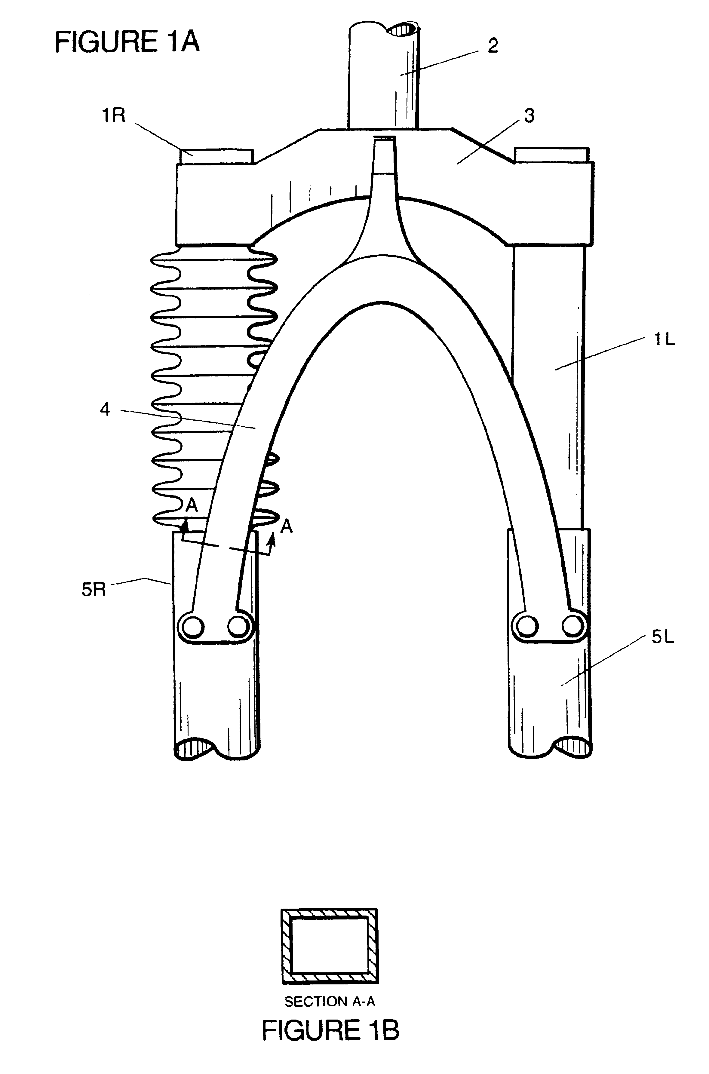
This invention relates to front fork, telescoping type suspension systems for bicycles. The main focus of the invention is the brake bridge assembly, the fork crown assembly and the joinder of these assemblies to form the fork suspension. The brake bridge assembly serves two main functions: 1) it provides a stiff structural connection between the right and left telescoping struts, to reduce wheel wobble during high speed wheel impacts, and 2) it provides a structural support for the brake cable stop. The invention provides for increased stiffness and lower stresses in the brake bridge, which translates into improved directional stability for the front wheel, less displacement for the brake cable stop .(when the brake loads are applied) and improved fatigue life for the assembly. It also provides for a simpler and less expensive means for mounting the brake bridge to the fork assembly. The invention also encompasses the fork crown producing a lightweight structure with high torsional and bending rigidity. The connections of the stanchions to the crown are achieved through a variety of methods including, (a) interference fit and bonding, (b) collet assembly and (c) "pinch-bolt" connections.

Description

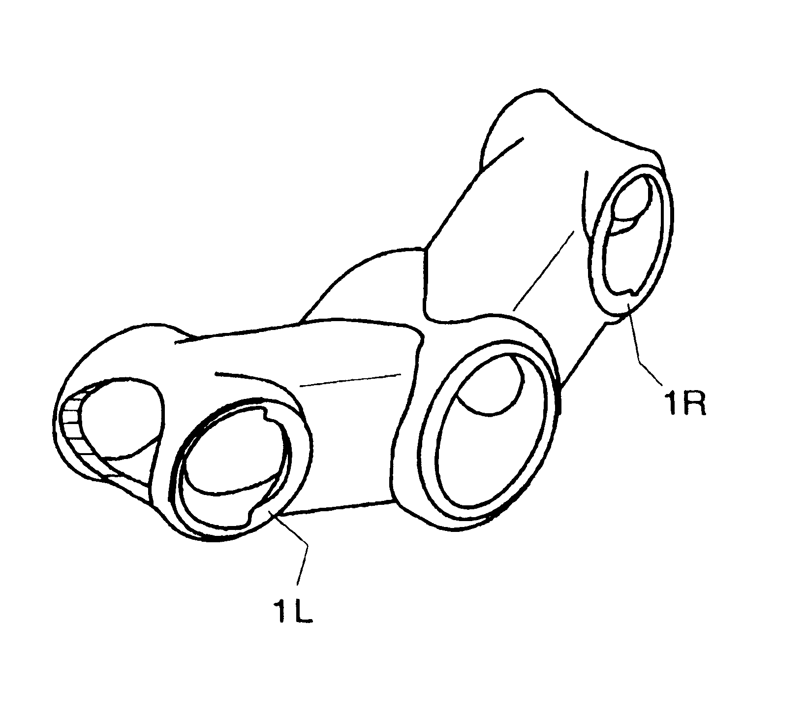
INTRODUCTIONThis invention relates to front fork, telescoping type suspension systems for bicycles. The invention is comprised of an improved fork crown, a brake arch structure and attaching means to other fork components. The crown structure is that part of the suspension that connects the stanchion tubes (the upper part of the telescoping assembly) to the steerer tube. The brake arch attaches the upper portion of the right sliding fork leg or strut to the upper portion of the left sliding fork leg or strut, as well as supporting the brake cable stop and brake caliper assembly (in the case of cantilever brakes). The invention provides a simple and inexpensive means for reducing the overall fork weight and at the same time improving the bending and torsional stiffness and strength of the overall fork, and specifically the fork crown and brake arch components.The invention provides an improved method for mounting the stanchion tubes to the fork crown and lower fork tubes to the brake...

Claims


Application Information

Patent Timeline
IPC IPC(8): B62K19/00B62K19/30B62K25/08
CPCB62K19/30B62K25/08Y10S188/01
Inventor VOSS, DARRELL W.KLEIN, GARY G.
Owner VOSS DARRELL W
Learn More