
Card edge connector with symmetrical board contacts

a card edge connector and symmetrical board technology, applied in the direction of coupling device connection, coupling protective earth/shielding arrangement, coupling/disengagement of coupling parts, etc., can solve the problems of low circuit density, complex operation of assembling terminals into the connector housing, and unoptimized electrical characteristics, etc., to achieve improved card edge connectors, high circuit density, and high circuit density

Inactive Publication Date: 2005-05-17
MOLEX INC
View PDF54 Cites 10 Cited by
  • Summary
  • Abstract
  • Description
  • Claims
  • Application Information

AI Technical Summary

Benefits of technology

[0014]An object of the present invention is to provide an improved card edge connector. Other objects are to provide a connector with low inductance that can achieve an impedance match with associated circuit assemblies; to provide a connector having minimum cross talk between signal circuits; to provide a connector having high circuit density; to provide a connector that is robust although small; to provide a mechanically and electrically reliable connector that can be manufactured and assembled inexpensively; and to provide an improved card edge connector overcoming disadvantages of connectors used in the past.

Problems solved by technology

These trends create problems for electrical connectors such as edge card connectors that are used to removeably mount a circuit card on a circuit board.
This connector has important advantages such as reducing the peak card insertion force, but has electrical characteristics that are not optimized for higher speed digital signals.
This approach defeats the goal of increased circuit density.
Although this arrangement has advantages, three different terminal shapes are required, and the operation of assembling terminals into the connector housing is complex.

Method used


Image

  • Card edge connector with symmetrical board contacts
  • Card edge connector with symmetrical board contacts
  • Card edge connector with symmetrical board contacts

Examples


Embodiment Construction

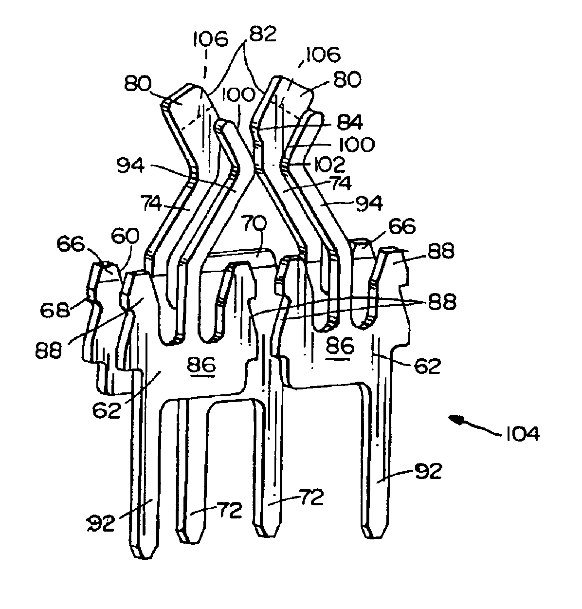
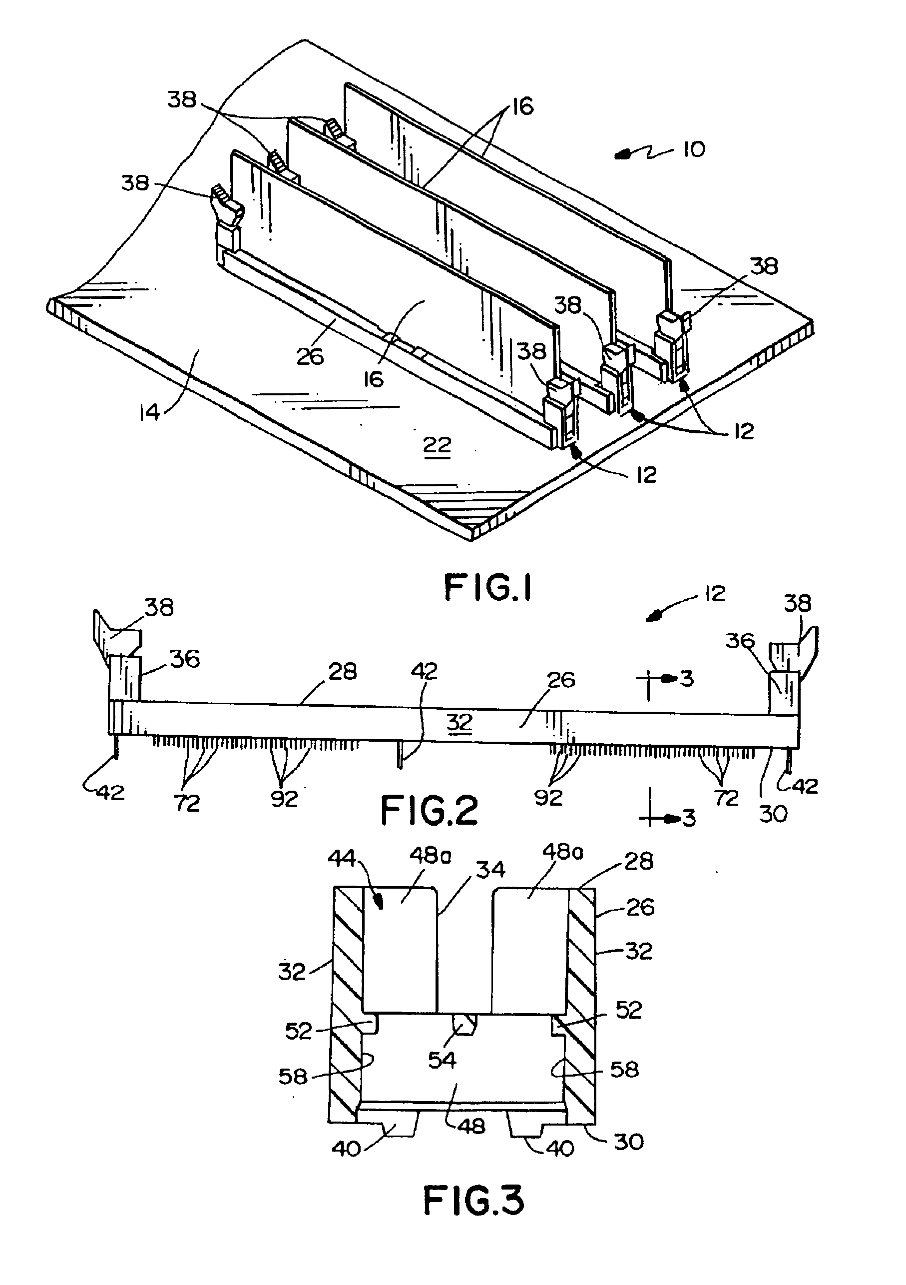
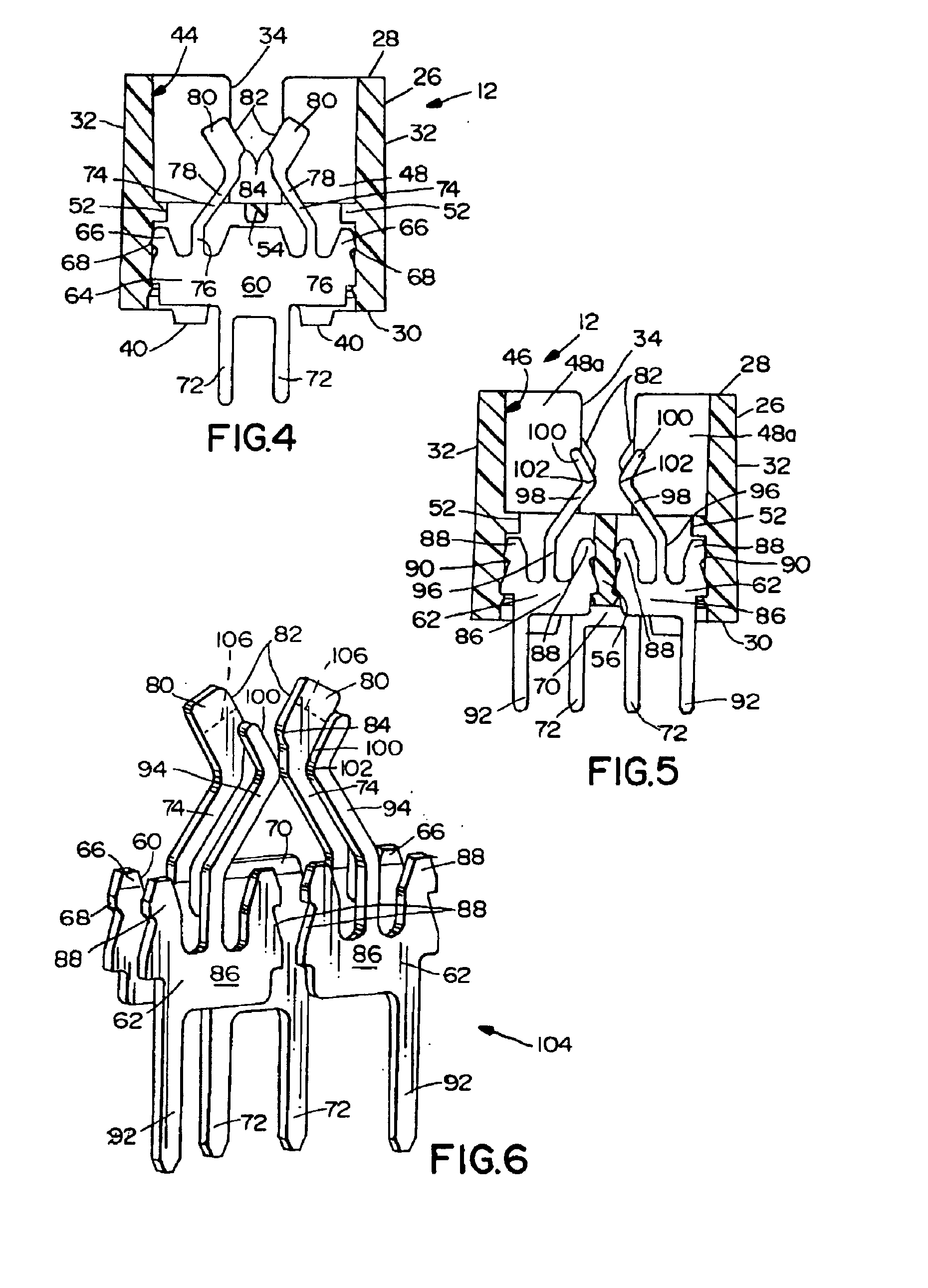
[0026]PREFERRED EMBODIMENTS Having reference now to the drawings, in FIG. 1 there is illustrated a circuit assembly generally designated as 10 and including three card edge connectors, each generally designated as 12, constructed in accordance with the principles of the present invention. The circuit assembly 10 includes a printed circuit board 14, for example, a computer motherboard. The card edge connectors 12 are mounted on the circuit board 14 and removeably receive printed circuit cards 16, for example, memory modules with random access memory available to the motherboard 14. The card edge connector provides circuit paths so that power, ground and digital signals can be transferred between the circuit board 14 and the circuit cards 16.

[0027]The pertinent structure of the circuit card 16 and the circuit board 14 are shown in FIGS. 8 and 9. The card 16, of which a fragment is seen in FIG. 8, includes an edge 18 that mates with the card edge connector 12. A series of conductive co...


PUM


Abstract

A card edge connector for mounting on a circuit board and removeably receiving a circuit card includes an elongated housing defining a card receiving slot. Numerous terminal receiving cavities intersect and extend to both sides of the slot. Alternate cavities include stamped references (ground or power) terminals and signal terminals, all having downwardly extending board contacts and upwardly extending spring arms. There are numerous similar sets of face to face contacts, each including a reference contact parallel to and substantially overlying an opposed pair of signal contacts. The upwardly extending reference terminal spring arms include oversize pad portions for reducing crosstalk by increasing coupling between the reference and signal terminals. The circuit paths to the circuit board are in an array symmetrical about the centerline of the circuit card, with parallel inner lines of circuits containing only reference contacts and outer lines of circuits containing only signal contacts.

Description

BACKGROUND OF THE INVENTION[0001]The present invention relates to electrical connectors for printed circuit boards, and more particularly to an improved card edge connector for removeably connecting a circuit card to a circuit board.DESCRIPTION OF THE PRIOR ART[0002]Devices such as computers using printed circuit boards are exhibiting increasing circuit densities and operate at increasing frequencies. For example, the speed of high frequency digital signals traveling between a computer motherboard and densely populated memory module printed circuit cards on an associated circuit board are becoming higher. These trends create problems for electrical connectors such as edge card connectors that are used to removeably mount a circuit card on a circuit board.[0003]With increasing circuit density, the electrical connectors and the electrical terminals they include are smaller. The terminals must nevertheless be sufficiently flexible and strong to provide reliable contact with a circuit c...

Claims


Application Information

Patent Timeline
Patent Type & Authority Patents(United States)
IPC IPC(8): H01R12/00H05K1/00H01R12/72H01R13/62H01R13/6471H01R13/6474H01R13/648H01R13/652H01R24/00H01R107/00
CPCH01R12/721H01R13/6471H01R13/6474H01R12/70H01R12/72
Inventor WALSE, ALAN S.LANG, HAROLD KEITHPANELLA, AUGUSTO P.TRINER, IRVIN R.TUNG, SHYH-LIN
Owner MOLEX INC
Learn More