Al technical title is built by PatSnap Al team. It summarizes the technical point description of the patent document.
a jaw biopsy and forcep technology, applied in the field of biopsy forceps, can solve the problems of complex construction of devices, requiring the manufacturing and machining of precise miniaturized components, and therefore generally quite expensive, and requiring expensive machining
Inactive Publication Date: 2006-11-28
BOSTON SCI MIAMI CORP
View PDF32 Cites 92 Cited by
Summary
Abstract
Description
Claims
Application Information
AI Technical Summary
This helps you quickly interpret patents by identifying the three key elements:
Problems solved by technology
Method used
Benefits of technology
[0015]The present invention comprises an improvement in biopsy forceps wherein a pair of jaws are formed from a casting. Each jaw of the pair of jaws of the biopsy forceps may be a duplicate of the other jaw. Each jaw is somewhat hemispherically shaped having an elongated portion which extends proximally into a cutter tang. Each cutter jaw has a generally U-shaped distalmost end on which is defined a plurality of radially disposed teeth. The teeth on one side of the longitudinal centerline of the jaw are displaced by one-half pitch from the corresponding teeth on the other side of the longitudinal centerline on that jaw. The displacement by one-half pitch of the teeth on one side of the jaw relative to those corresponding teeth on the other longitudinal side of the jaw permits the same casting to be used for both the upper and lower jaws. The radially disposed array of teeth on each of the jaws permits a self-aligning feature therewith, thus compensating for the slightly looser tolerances found in the casting manufacturing technique.
[0017]The handle comprises a central shaft about which a displaceable spool is disposed. The central shaft has a longitudinally directed stepped diameter bore extending therein on its distal end, and a thumb ring on its proximalmost end. The proximal end of the coil extends into the bore on the proximal end of the central shaft. The bore in the central shaft on the handle has a stepped configuration. The distal end of the bore having a slightly larger diameter than the second or intermediate bore, or the third or proximal end of the bore in the central shaft. A locking coil is arranged to mate within the stepped large outer diameter (distal end) of the central shaft. The locking coil has an inner diameter which is slightly smaller than the outer diameter of the main coil extending from the cutter jaw assembly to the handle. The main coil is screwed into the locking coil disposed within the central shaft. A sheath which acts as a strain relief, is disposed distally of the locking coil about the main coil within the central shaft. The sheath holds the locking coil within the first stepped bore in the central shaft. The strain relief is bonded to the bore of the central shaft. The proximalmost end of the joggled pull wires extend through the proximal end of the main coil and into a thin anti-kink tube in the narrowest third stepped bore in the central shaft. The cross pin fits through a slot at the midpoint of the central shaft. The slot is in communication with the third bore therein. A cross pin mates with the slot across the central shaft. The proximalmost end of the joggled pull wires are locked into an opening in the cross pin. The ends of the cross pin mate with slots in the spool so as to facilitate corresponding motion in the joggled pull wires.
[0019]Movement of the spool distally with respect to the central shaft effectuates a compression on the pull wire thus causing arcuate movement of the tangs on the proximal end of each jaw to force a pivoting motion about the clevis pin thus opening the respective jaws.
Problems solved by technology
Ordinarily, these devices are of complicated construction, requiring the manufacturing and machining of precise miniaturized components, which are therefore generally quite expensive.
The jaws shown in this patent are made from stainless steel and likewise, require expensive machining.
Method used
Image
Click on the blue label to locate the original text in one second.
Reading with bidirectional positioning of images and text.
Examples
Embodiment Construction
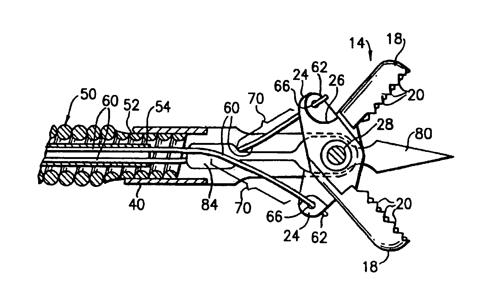
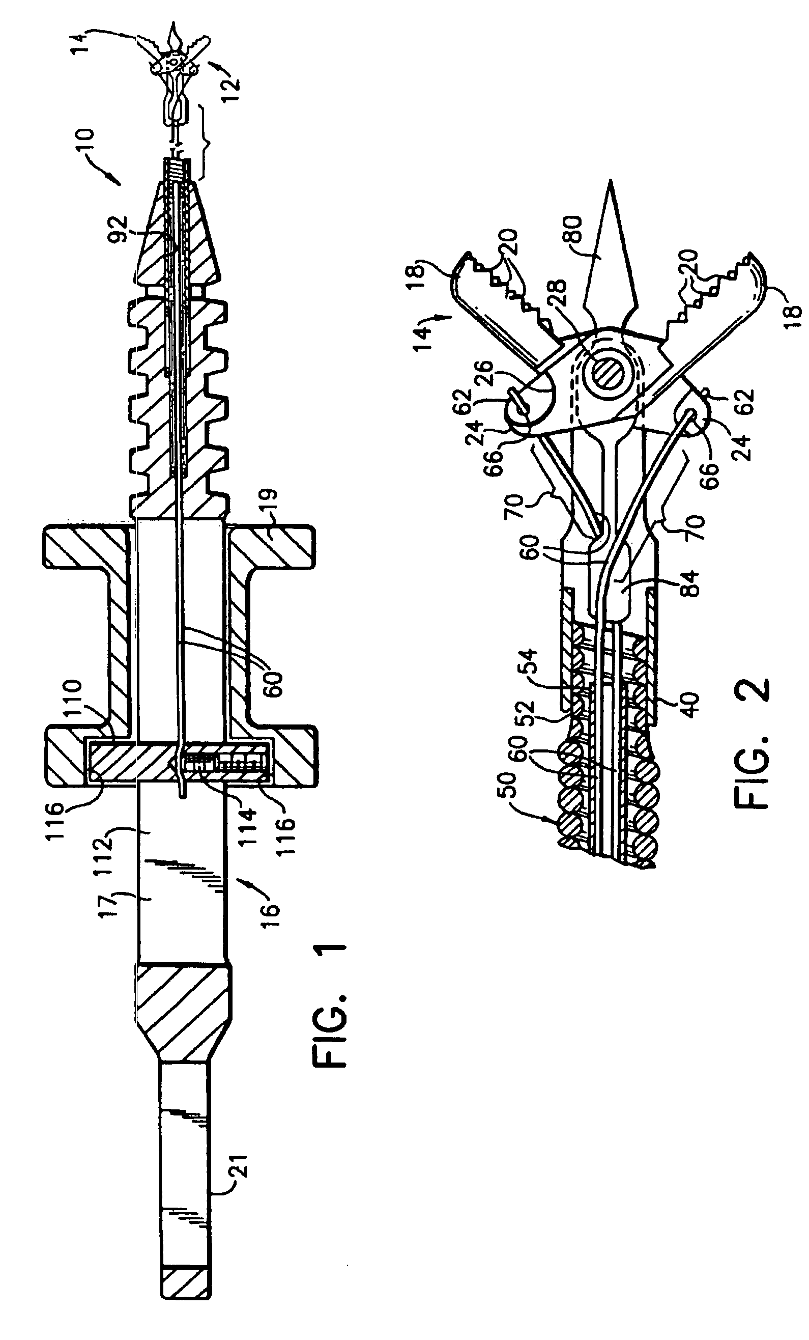
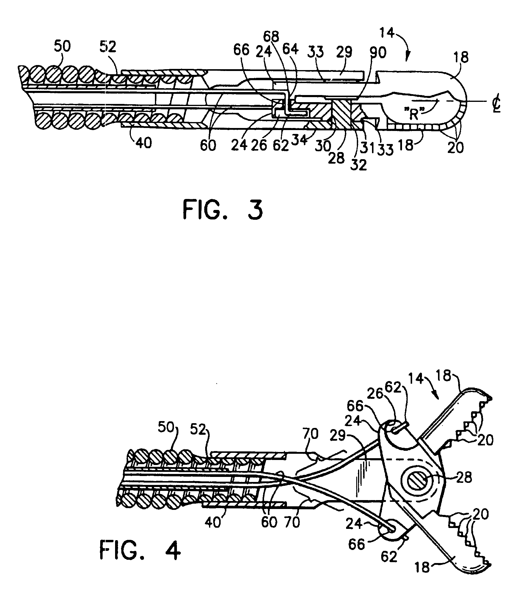
[0028]Referring now to the drawings in detail and particularly to FIG. 1, there is shown a biopsy forceps assembly 10, having a distal end 12, comprising a jaw assembly 14, and a proximal end 16 comprising a handle 17, spool 19 and thumb ring 21 for manipulation of the assembly. The jaw assembly 14 comprises a pair of jaws 18, each of which is a duplicate of the other. Each jaw 18 as may be seen in FIGS. 2 and 3, is a generally elongated somewhat hemispherically shaped structure having a distalmost end and a proximalmost end. Each jaw 18 has on its distalmost end, an array of teeth 20 generally radially directed about a point “R”, as exemplified in FIG. 3. Each jaw 18 has a generally longitudinal centerline as may be seen in FIGS. 3 and 5. The teeth 20 on one side of the longitudinal centerline of each jaw 18 being displaced by one half pitch from the corresponding teeth 20 on the other side of the longitudinal centerline on that jaw 18. The displacement by one half pitch by the tee...
PUM
Property
Measurement
Unit
triangular shape
aaaaa
aaaaa
elongated hemispherical shape
aaaaa
aaaaa
angle
aaaaa
aaaaa
Abstract
A biological forceps device for the taking of tissue samples from a body, comprising a flexible main coil attached at its distal end to a pair of homologous cast jaws. The jaws have radially arranged teeth on their distalmost end. The jaws are opened and closed by attachment to a pair of pull wires which extend through the main coil, into a handle at its proximal end, the handle has a spool which slides about a central shaft attached to the main coil. The spool is attached to the pull wires, so that movement of the spool with respect to the central shaft, effectuates a force on the proximal ends of the levered jaws, to open and close them, appropriately.
Description
[0001]Notice: This is a continuation reissue of application Ser. No. 10 / 074,012, filed Feb. 14, 2002, which is a reissue application of U.S. Pat. No. 6,024,708. [0002]This is a continuation division of application Ser. No. 08 / 458,215, filed Jun. 2, 1995, now U.S. Pat. No. 5,666,965 which is a continuation of Ser. No. 07 / 837,046 filed Feb. 18, 1992, now U.S. Pat. No. 5,507,296, which is a continuation of Ser. No. 07 / 521,766 filed May. 10, 1990 now U.S. Pat. No. 5,133,727.BACKGROUND OF THE INVENTION[0003]This invention relates to biopsy forceps and more particularly to unique handler actuation wire and homologous jaw construction for those forceps.[0004]A number of different types of biopsy forceps are in common use, typically in conjunction with endoscopic assistance. Ordinarily, these devices are of complicated construction, requiring the manufacturing and machining of precise miniaturized components, which are therefore generally quite expensive.[0005]One early example of flexible ...
Claims
Application Information
Patent Timeline
Application Date:The date an application was filed.
Publication Date:The date a patent or application was officially published.
First Publication Date:The earliest publication date of a patent with the same application number.
Issue Date:Publication date of the patent grant document.
PCT Entry Date:The Entry date of PCT National Phase.
Estimated Expiry Date:The statutory expiry date of a patent right according to the Patent Law, and it is the longest term of protection that the patent right can achieve without the termination of the patent right due to other reasons(Term extension factor has been taken into account ).
Invalid Date:Actual expiry date is based on effective date or publication date of legal transaction data of invalid patent.