Optical system of laser ruler

An optical system and laser ruler technology, which is applied in the field of laser rulers, can solve problems such as increased system instability factors, increased system manufacturing costs, and reduced system reliability, achieving high mass production of component processing, no moving components, and simple structure Effect

Inactive Publication Date: 2011-07-27
ASIA OPTICAL CO INC
View PDF1 Cites 0 Cited by
  • Summary
  • Abstract
  • Description
  • Claims
  • Application Information

AI Technical Summary

Problems solved by technology

These additional mechanisms and components will add unstable factors to the system, reduce the reliability of the system, and also increase the manufacturing cost of the system
Moreover, although the use of optical fiber facilitates the setting of the mechanism position, the energy will inevitably be lost, which will reduce the utilization rate of the overall light energy.

Method used


Image

  • Optical system of laser ruler
  • Optical system of laser ruler
  • Optical system of laser ruler

Examples


Embodiment Construction

[0023] The detailed description and technical content of the laser ruler optical system of the present invention are now described as follows in conjunction with the accompanying drawings:

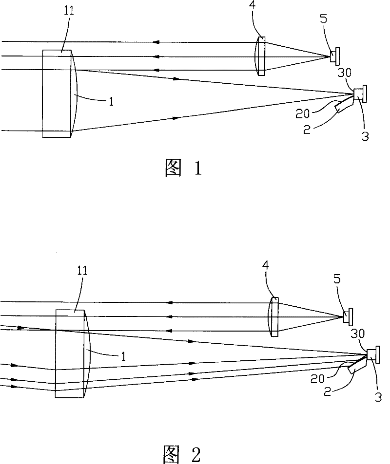
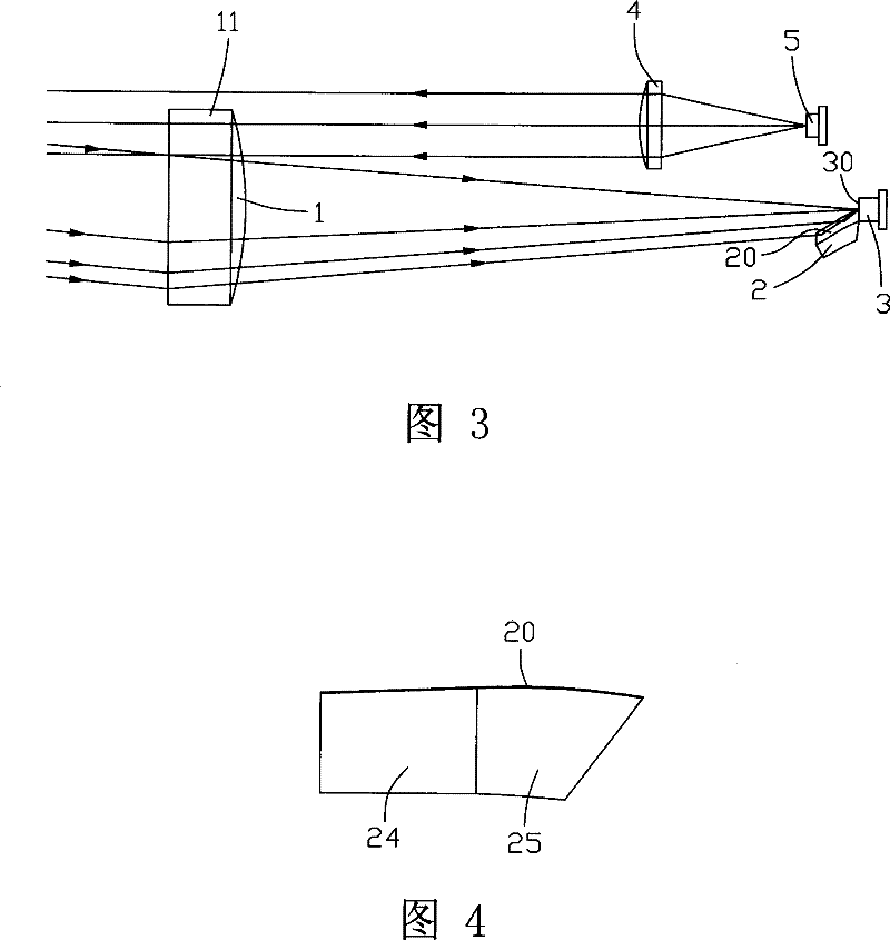
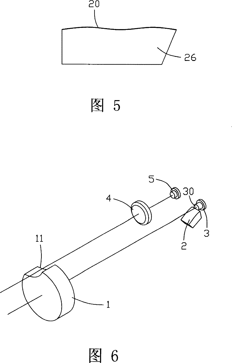
[0024] see Figure 6 , the optical system of the laser ruler of the present invention is an optical system for measuring the distance of an object to be measured, which includes a laser light source 5, a lens assembly 4 at the transmitting end, a lens assembly 1 at the receiving end, and a curved reflective assembly with a reflective curved surface 20 2 and a light receiving component 3 having a light receiving surface 30.

[0025] Such as figure 1 , figure 2 and image 3 shown in figure 1 The middle is to show the optical path diagram when the laser ruler of the present invention is used to measure a long-distance target, and figure 2 Then display a light path diagram when measuring a short-distance target, image 3 and figure 2 similar, but showing figure 2 The view formed ...


PUM


Abstract

An optical system of laser rule is featured as sending light emitted by laser source to object to be tested via lens set of emission end, forming a receiving light by reflected light of object to be tested via lens set of receiving end, entering said receiving light directly to light receiving surface of light receiving component and simultaneously reflecting residual light being not entered directly to said light receiving surface also to light receiving surface of light receiving component by reflecting curved surface of curved surface reflection component.

Description

【Technical field】 [0001] The invention relates to a laser encoder, in particular to a structure of an optical system of the laser encoder. 【Background technique】 [0002] Laser ruler (or laser range finder) is one of the important devices that use laser light source to measure distance. The commonly used laser encoder uses a laser light source to send modulated light to the target, and the target reflects the laser signal to a light receiving component. The light receiving component is usually an Avalanche Photo Diode (APD), which converts the light signal into electric signal. The optical system of the laser encoder calculates half of the time difference between the sending pulse and the receiving pulse, and then multiplies it by the speed of light to obtain the distance value. [0003] However, there are still many technical difficulties in the application of laser ranging in short-distance and high-precision fields, such as the short-distance light receiving problem, th...

Claims


Application Information

Patent Timeline
Patent Type & Authority Patents(China)
IPC IPC(8): G01C3/00
Inventor 陈慧卿陈海华
Owner ASIA OPTICAL CO INC
Why Eureka
Try Eureka