
Digital imaging device optimized for color performance

a digital imaging and color performance technology, applied in the field of digital imaging, can solve the problems of color reproduction errors, spectral response that prevents the replication of cmfs, and inability to match inevitably, so as to minimize the variation of color reproduction from one camera to the nex

Inactive Publication Date: 2007-07-03
INTELLECTUAL VENTURES FUND 83 LLC
View PDF6 Cites 13 Cited by
  • Summary
  • Abstract
  • Description
  • Claims
  • Application Information

AI Technical Summary

Benefits of technology

[0015]Besides providing an optimal level of color correction, the present invention has the advantage that the color reproduction variation from one camera to the next is accordingly minimized. This reduces the occurrence of color nonuniformity between the same digital images captured by different digital cameras.

Problems solved by technology

Failure to achieve this goal will result in color reproduction errors.
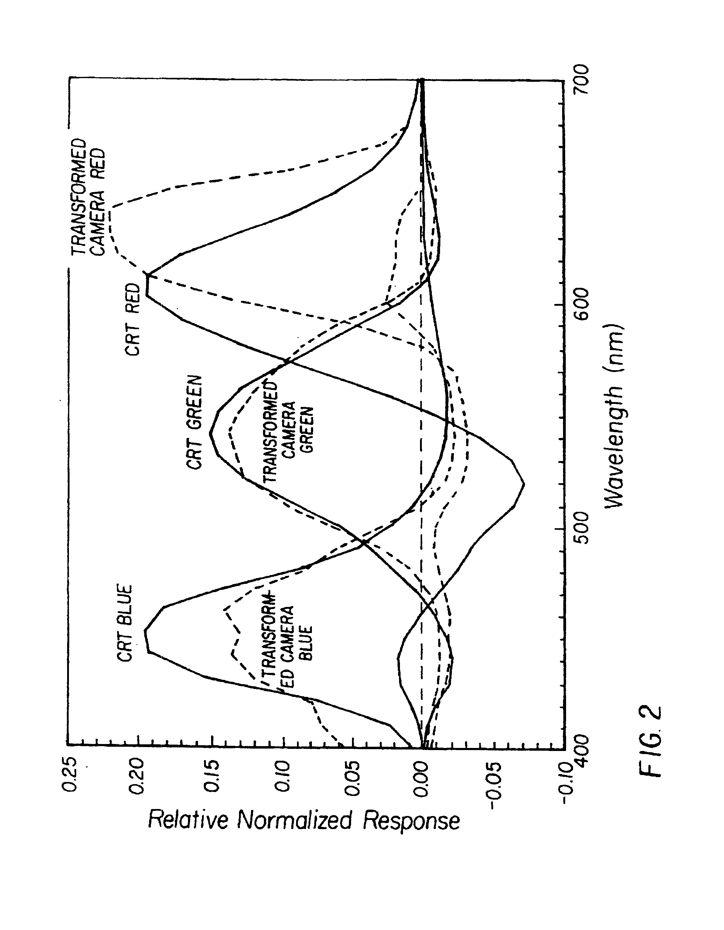
One practical limitation in the selection of a set of CMFs for the camera is the restriction that they be all positive, whereas the CMF's decreasing a color CRT typically have negative lobes.
Another practical restriction in the selection of a set of camera CMF's is the need to minimize the size of the off-diagonal coefficient in the color-correction matrix since these are directly responsible for degrading the noise performance of the imaging system.
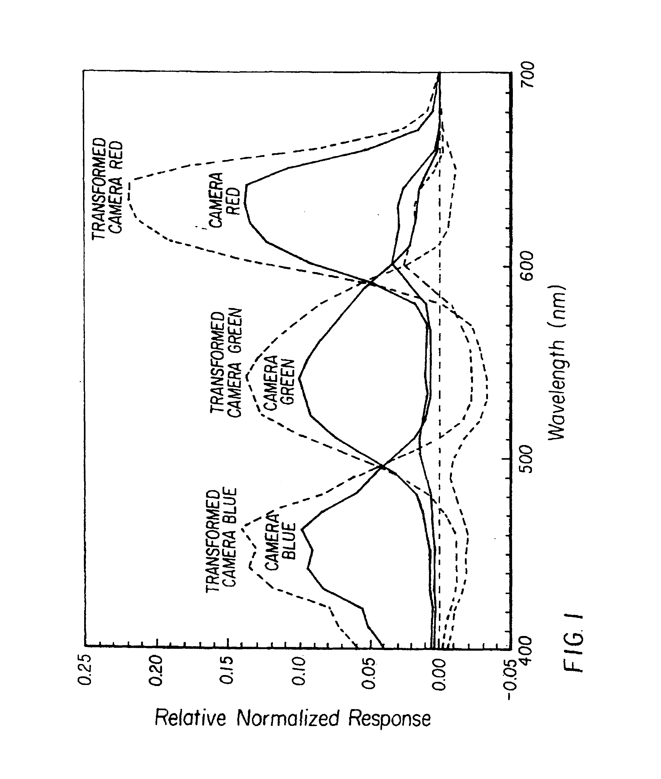
It can be seen that elements in a real camera have errors in spectral response that prevent replication of CMFs regardless of the transformation.
Errors are normally spread among all colors in a way that minimizes color errors, but the result inevitably is not a perfect match, as seen particularly in the transformed camera red spectral response in FIG.
Unfortunately, small variations in optical component spectral characteristics, even within the same family of cameras, can produce noticeable color differences in the output image.
Heretofore, the approaches taken do not account for variations in optical component spectral characteristics from individual imaging device to individual imaging device.

Method used


Image

  • Digital imaging device optimized for color performance
  • Digital imaging device optimized for color performance
  • Digital imaging device optimized for color performance

Examples


third embodiment

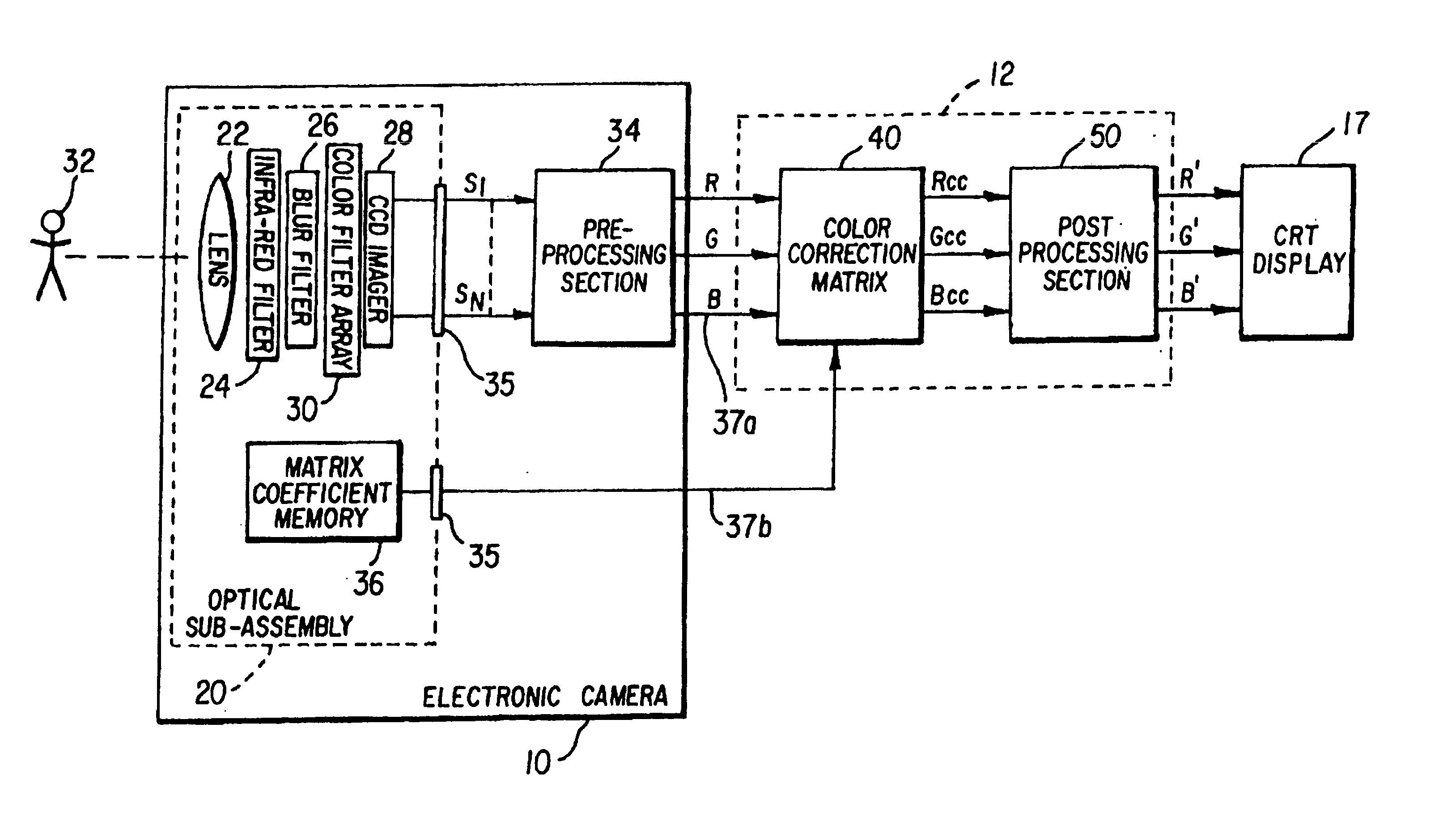
[0034]FIG. 5 illustrates the invention wherein the color-correction matrix coefficients for the matrix operation 40 are stored in a digital memory 38 located somewhere within the camera 10 but not necessarily on the optical sub-assembly 20. In this embodiment, the aforementioned advantages in the production and service environment are not realizable for the color reproduction accuracy and consistency goals of the invention are not compromised.

fourth embodiment

[0035]FIG. 6 illustrates the invention wherein the lens 22 is not physically part of the optical sub-assembly and many, in fact, be removable as is the case of a camera with interchangeable lenses. In this situation the camera of optical sub-assembly, depending on where the color-coefficient matrix digital memory 38 is located, is calibrated using a lens with a spectral response representing the average of the spectral responses of all lenses that are anticipated to be used with the camera. This represents only a slight compromise since the lens does not contribute significantly to variations in color reproduction performance.

[0036]The present invention has been described thus far with regard to a series of preferred embodiments outlining the location of the color-correction matrix coefficients within the camera as well as their application in the image processing path. FIG. 7 illustrates a general method for obtaining these coefficients. A color chart 72 containing colors represent...


PUM


Abstract

A digital imaging device captures an image and generates a color signal from the image for application to an output device having specific color sensitivities, the imaging device further being one of many devices of the same type useful with the output device. The digital imaging device, for example a digital camera, includes a color sensor for capturing the image and generating a color signal from the captured image, the color sensor having predetermined spectral sensitivities, and an optical section that is interposed in the image light directed to the color sensor, the optical section also having predetermined spectral characteristics. The combination of the spectral sensitivities of the color sensor and the spectral characteristics of the optical section uniquely distinguish this particular imaging device from other imaging devices of the same type. By providing a set of matrix coefficients uniquely determined for this imaging device, the matrix coefficients optimally correct the spectral sensitivities of the color sensor and the spectral characteristics of the optical section for the color sensitivities of the output device.

Description

[0001]This application is a reissue application for U.S. Pat. No. 5,668,596 issued on Sep. 16, 1997 on U.S. Ser. No. 08 / 608,649 filed Feb. 29, 1996FIELD OF THE INVENTION[0002]This invention pertains to the field of digital imaging and, more particularly, to the optimization of the color performance of digital imaging device, such as digital cameras and scanners.BACKGROUND OF THE INVENTION[0003]Correction matrices are useful in a variety of color imaging applications to effect color conversion or correction. For instance, a conversion matrix is used to convert red, green, and blue video signals into Y (luminance) and I, Q (chrominance) signals. A color correction matrix is used to correct the spectral sensitivities of a video camera for the chromaticities of the phosphor set of the particular display in use. Another use is with film-to-video conversion, a process in which a color correction matrix operates on the film scanning signals to correct the film colorimetry for video display...

Claims


Application Information

Patent Timeline
IPC IPC(8): H04N5/228H04N9/04H04N9/67
CPCH04N2209/046H04N25/447H04N23/85H04N9/67
Inventor VOGEL, RICHARD M.
Owner INTELLECTUAL VENTURES FUND 83 LLC
Learn More