Magnetic non-destructive method and apparatus for measurement of cross sectional area and detection of local flaws in elongated ferrous objects in response to longitudinally spaced sensors in an inter-pole area

a technology of elongated ferrous objects and cross sectional area, which is applied in the direction of measuring devices, instruments, and material analysis by electric/magnetic means, can solve the problems of increasing the magnetic flux density in the inter-pole area, lma measurement error, and reducing the influence of temperature variation on the magnetizing device, so as to increase the accuracy of cross sectional area measurement and local flaw detection, and increase the reliability of lf detecting

Inactive Publication Date: 2008-03-25
INTRON PLUS
View PDF3 Cites 24 Cited by
  • Summary
  • Abstract
  • Description
  • Claims
  • Application Information

AI Technical Summary

Benefits of technology

[0013]An object of the present invention is the solution of the problem of increasing the accuracy of cross sectional area measurements and local flaw detection in steel wire ropes. A further object of the invention is increasing the reliability of LF detecting in elongate ferrous objects.
[0015]The rope cross sectional area is defined by a sum of the signals from the sensor pair. When the rope cross sectional area is changed, the magnetic fluxes through the rope and through the area surrounding the rope are redistributed. In particular, loss of the rope cross section metallic area (LMA) leads to an increase in magnetic flux leakage within the inter-pole space round the rope, which increases magnetic flux density in the inter-pole area. The relative increase of the leakage flux occurs significantly more than the relative decrease in the base flux. Therefore, a resulting signal change from the sensors within the inter-pole space is significantly more than the signal change of the sensors in the gaps between the poles and the rope. This provides an increased LMA measurement accuracy.
[0016]A further increase in accuracy is provided by a subtraction of additional magneto-sensitive sensor signals from the sum of the sensor pair signals. The additional sensor signal is provided from a sensor located in a gap between the rope under test and a pole of the magnetizing device. That is, along a radius extending from the longitudinal axis of the rope, there is the rope surface, the additional sensor and then the pole of the magnetizing device. The resulting second signal difference is used to measure LMA. Thus, an LMA measurement error, from the instability of magnetic flux density round the rope, e.g. from the influence of temperature variation on the magnetizing device, is decreased.
[0017]The presence of a LF in the rope is detected by a first signal difference of sensors forming the pairs. When a rope section under test contains no LF, then signals from the sensors in a pair equal each other and the first difference of the signals is close to zero. If the section, containing a LF, gets to a sensitivity zone of one of the sensors in the pair, then magnetic field homogeneity is destroyed in the zone due to a local magnetic flux leakage induced by the LF. The pair of the first sensors is thus unbalanced and the first signal difference differs from zero. Unavoidable radial displacements of the rope during a test do not destroy magnetic field homogeneity. Due to this, the output signal of the sensor pair remains close to zero, thus a noise level, e.g. because of rope vibration, is low. An increased signal to noise ratio is thereby provided as well as LF detecting reliability.

Problems solved by technology

In particular, loss of the rope cross section metallic area (LMA) leads to an increase in magnetic flux leakage within the inter-pole space round the rope, which increases magnetic flux density in the inter-pole area.
Thus, an LMA measurement error, from the instability of magnetic flux density round the rope, e.g. from the influence of temperature variation on the magnetizing device, is decreased.

Method used


Image

  • Magnetic non-destructive method and apparatus for measurement of cross sectional area and detection of local flaws in elongated ferrous objects in response to longitudinally spaced sensors in an inter-pole area
  • Magnetic non-destructive method and apparatus for measurement of cross sectional area and detection of local flaws in elongated ferrous objects in response to longitudinally spaced sensors in an inter-pole area
  • Magnetic non-destructive method and apparatus for measurement of cross sectional area and detection of local flaws in elongated ferrous objects in response to longitudinally spaced sensors in an inter-pole area

Examples


Embodiment Construction

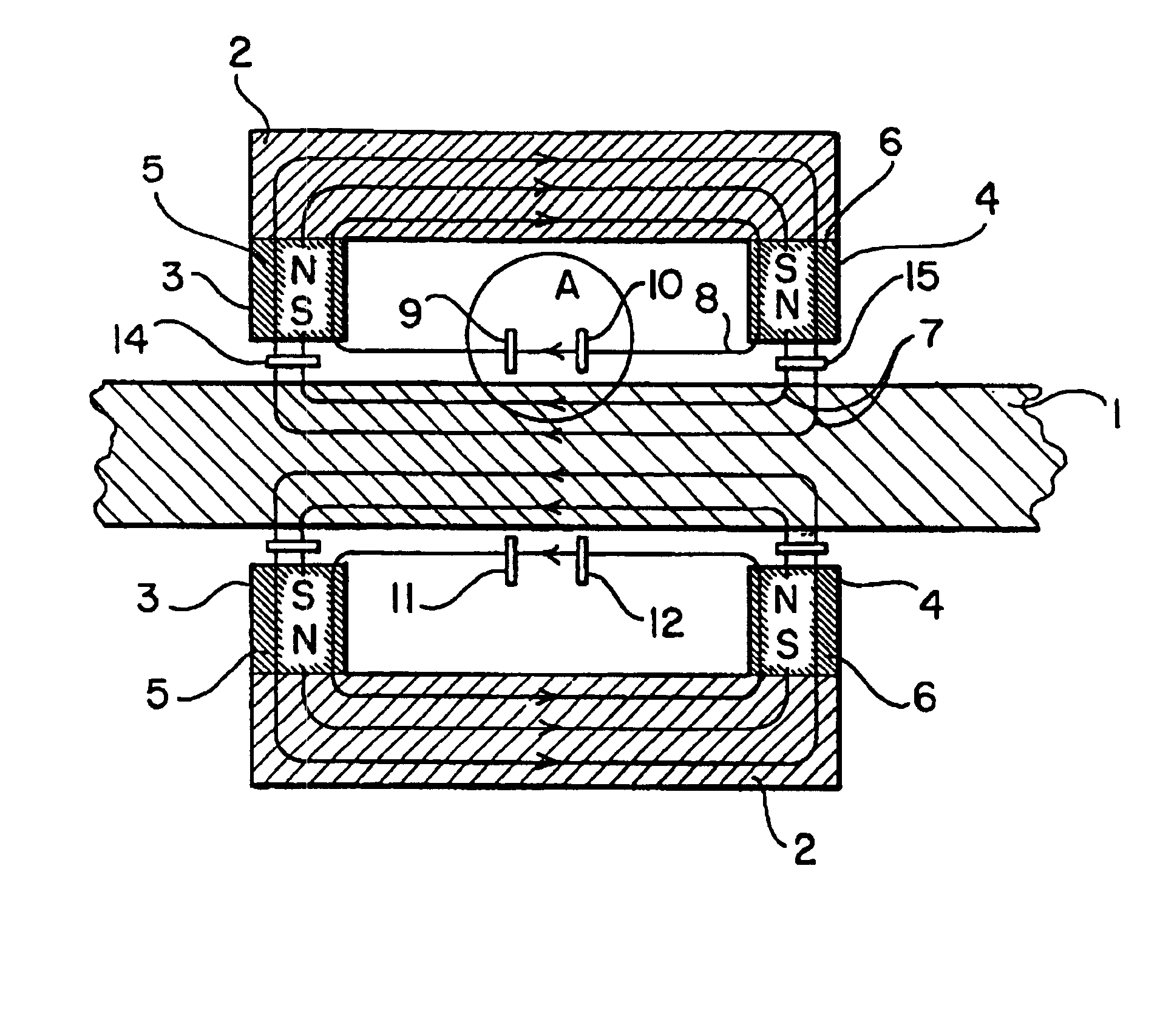
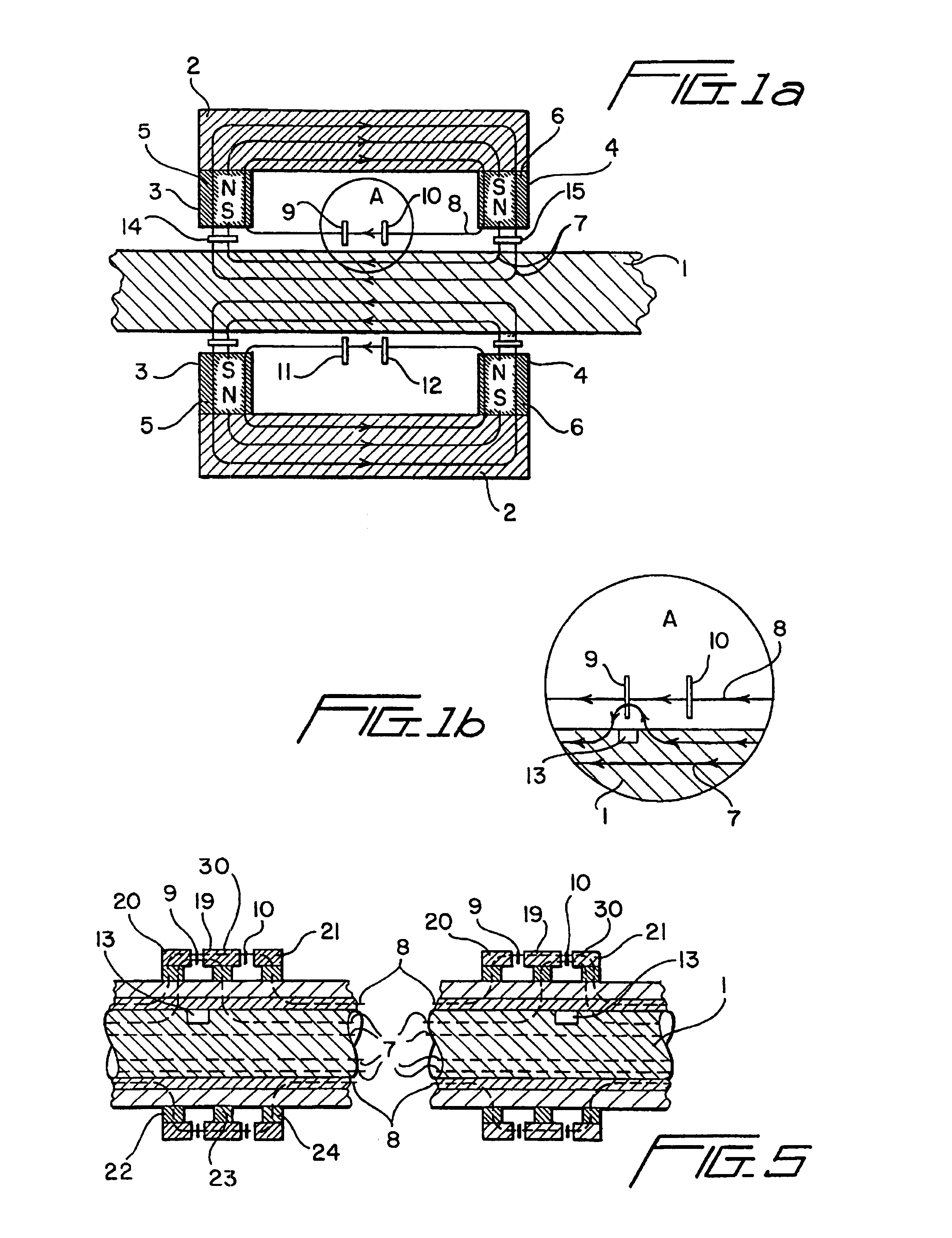
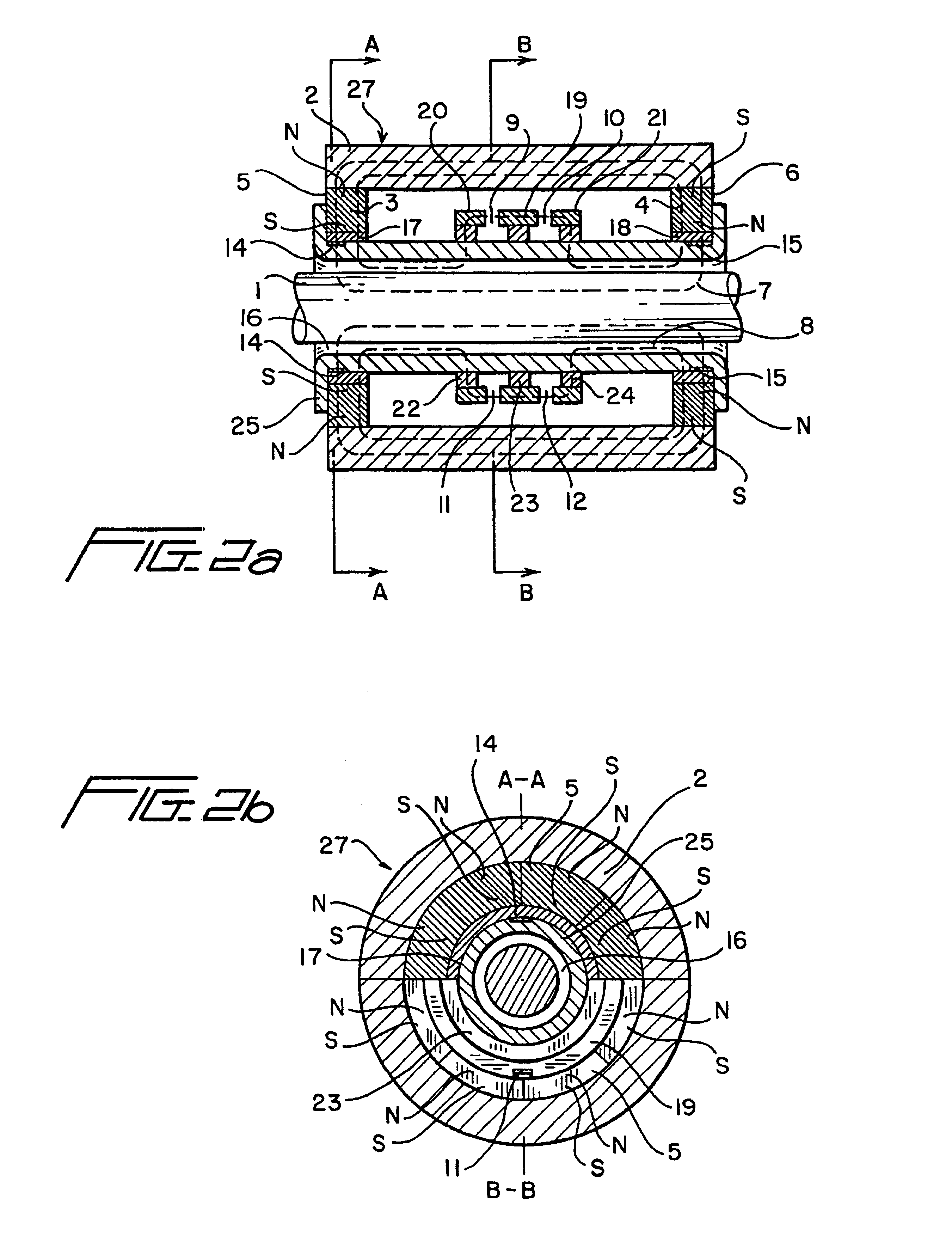
[0028]The present description is set forth in terms of the magnetic non-destructive measurement of a cross-sectional area of an elongated ferrous object such as a steel rod, tube, wire or wire rope. It is understood the cross section of these structures can define a circular, curvilinear, rectangular, triangular, or faceted profile. For purposes of description the term “rope” or “wire rope” shall be understood to encompass each of these structures. Since NDT of steel ropes in use is an actual problem, this particular case is set forth in an exemplary manner below.

[0029]Referring to FIG. 1, the magnetic flux through a rope 1 under test is provided by a magnetizing device 40 having a magnetic core 2 with spaced apart poles 3, 4 on the ends adjacent to and facing the rope 1. The poles 3, 4 are spaced along the longitudinal axis of the rope 1. The spaced apart poles 3, 4 thereby define an inter-pole area (or length) extending parallel to the longitudinal axis between the longitudinally ...


PUM

PropertyMeasurementUnit
distanceaaaaaaaaaa
magneticaaaaaaaaaa
magnetic fieldaaaaaaaaaa

Abstract

A magnetic non-destructive method and an apparatus for measurement of cross sectional area of elongated ferrous objects such as steel wire ropes and for detecting local flaws is disclosed. A section of a wire rope is magnetized by longitudinally spaced magnetic poles. A magnetic field parameter, e.g. magnetic flux density, is measured in, by at least, one pair of points between the poles of magnetizing device (in an inter-pole area) at the object under test surface. The pair of points is formed by two sensors placed in the inter-pole area along a direct line parallel to the rope axis. The rope cross sectional area corresponds to a sum of the sensor pair signals. Local flaws, such as broken wires and pitting corrosion in the rope, is detected by a first differences of signals of the sensor pair. At least one additional magneto-sensitive sensor is located radially inward of the poles and weight coefficient A depending on a nominal value of the rope cross sectional area is subtracted from the sum of signals of the sensor pair thereby providing a second difference of the signals corresponding to the rope cross sectional area. The coefficient A value is chosen to get the minimum value of the second signal difference while the magnetizing device and all the sensors are placed onto the rope having a nominal value of a cross sectional area. A sensor unit in the inter-pole area includes a magnetic core in form of three longitudinally spaced ferrous elements. Pairs of the sensors are located in the gaps along a direct line parallel to the rope. Two embodiments of the magnetic heads are disclosed: the hollow cylinder-shaped one and the U-shaped one.

Description

[0001]The present application claims priority benefits under 35 U.S.C. §119 to Russian Federation application N99126933 / 28 filed Dec. 17, 1999.[0002]1. Field of the Invention[0003]The present invention relates to the non-destructive testing of product quality, and in particular, to magnetic testing of elongated ferromagnetic objects like steel rods, tubes and wires to determine variances in a cross sectional area of object as well as the presence of local flaws.[0004]2. Background of the Invention[0005]A method and apparatus for magnetic non-destructive testing of elongated objects, e.g. steel ropes, by measurement of loss of metallic area (LMA) due to wearing and for local flaw (LF) detecting are described in U.S. Pat. No. 4,659,991, US C1. 324 / 241, Int.C1.G01N27 / 82, issuing in 1987. The method includes the axial magnetizing of the rope part by permanent magnets to a condition close to magnetic saturation and measuring the magnetic flux leakage variation near the rope surface by us...

Claims


Application Information

Patent Timeline
Patent Type & Authority Patents(United States)
IPC IPC(8): G01N27/82
CPCG01N27/82
Inventor SUKHORUKOV, VASILY VASILIEVICHBELITSKY, SERGUEI BORISOVICH
Owner INTRON PLUS
Why Eureka
Try Eureka