High-density fiber distribution frame

a fiber distribution frame and high-density technology, applied in the field of high-density fiber distribution frames, can solve the problems of unsatisfactory or excessive fiber optic cable displacement, bending and other forces, and prior art products that require substantial fiber displacemen

Inactive Publication Date: 2010-07-27
COMMSCOPE TECH LLC +1
View PDF45 Cites 138 Cited by
  • Summary
  • Abstract
  • Description
  • Claims
  • Application Information

AI Technical Summary

Benefits of technology

[0066]The benefits of the present invention include limited displacement of the fibers. In the prior art, when a tray containing several connectors is moved, the fibers are displaced axially by a substantial amount (e.g., about 3 inches). In the present invention, as a module 58 is moved up or down (about 1.5 inches) the fiber experiences very little axial movement with most of the movement accommodated by a lifting or lowering movement of the fiber transverse to the fiber's axis.

Problems solved by technology

One problem associated with prior art high-density fiber distribution frames is that the prior art products require substantial displacement of fibers when access to the fiber connectors is required.
Unnecessary or excessive displacement of fiber optic cables is undesirable.
As fiber optic cables are displaced, they are subject to bending and other forces.
As a fiber bends, the fiber can break resulting in loss of transmission through the fiber.
Since fibers carry extremely high signal rates, the breakage of a single fiber can result in a substantial loss of data or voice communications.

Method used


Image

  • High-density fiber distribution frame
  • High-density fiber distribution frame
  • High-density fiber distribution frame

Examples


Embodiment Construction

[0042]With reference now to the several drawing figures in which identical elements are numbered identically throughout, a description of the preferred embodiment of the invention will now be provided.

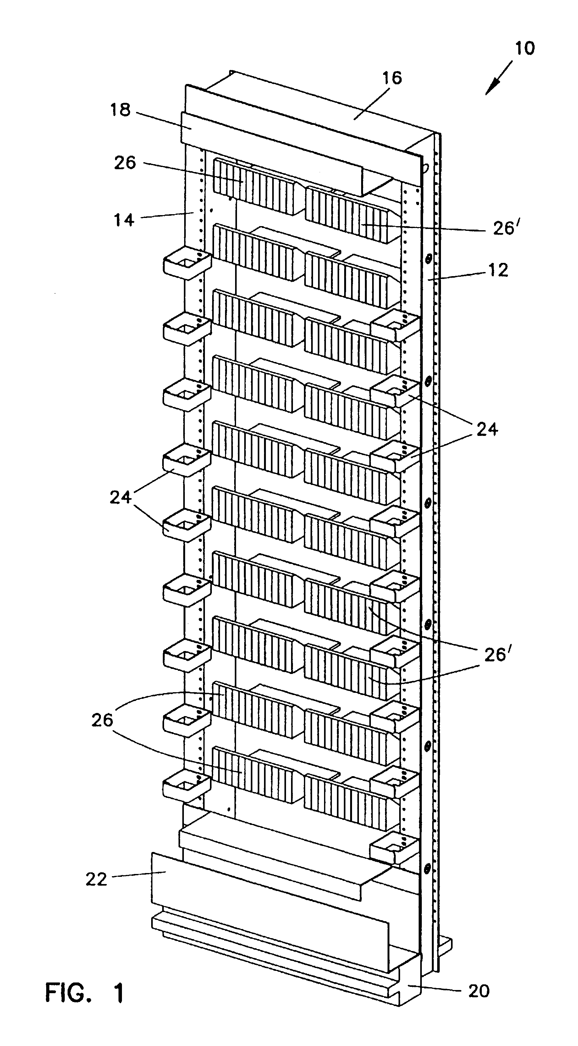
[0043]With initial reference to FIG. 1, a fiber distribution frame 10 is shown. The frame 10 includes spaced-apart side walls 12,14 connected at their upper ends by a top wall 16. Connected to the forward side of the top wall 16 is a trough 18 for carrying cables and the like as is conventional. The bottom of the frame 10 is provided with a pedestal 20 which also has secured to it a trough 22 for carrying cables and the like. The forward edges of the side walls 12,14 are provided with a plurality of clips 24 for holding fiber optic cables extending vertically in front of side walls 12,14.

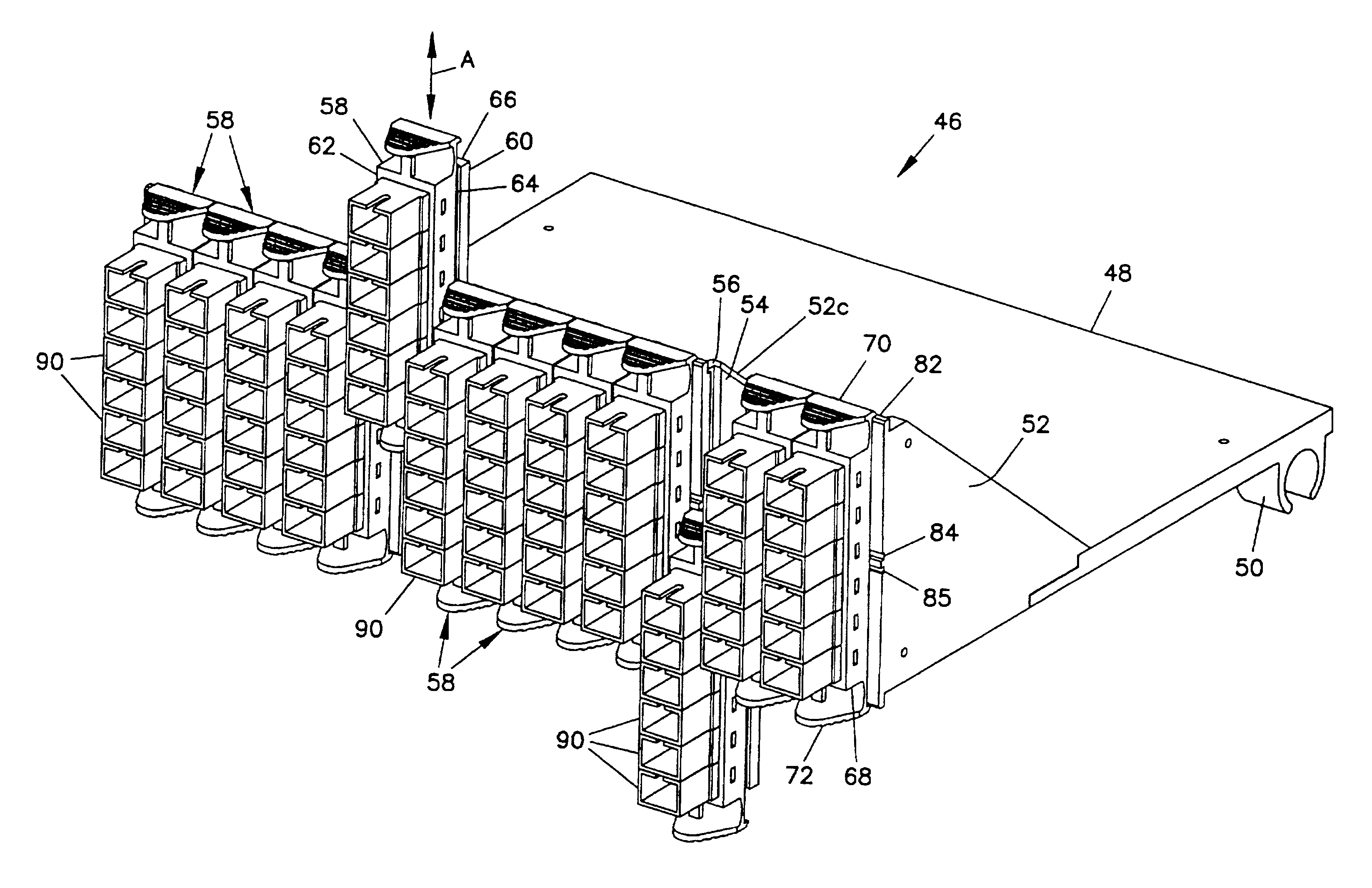
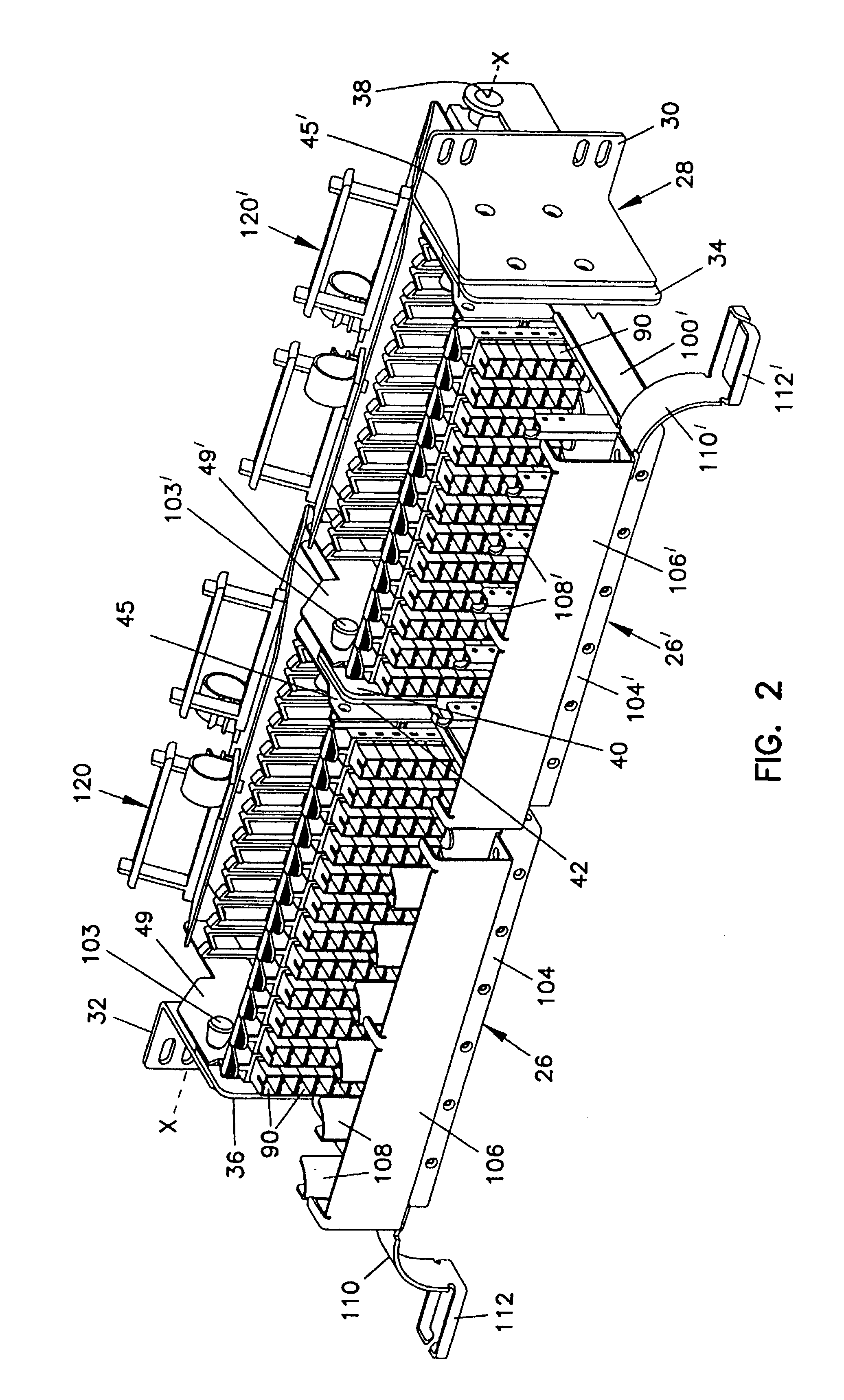
[0044]Contained within frame 10 between side walls 12,14 are a plurality of left and right mounting fixtures 26,26′ (schematically shown in FIG. 1). A detailed description of mounting fixtures 26,26′ i...


PUM


Abstract

A fiber distribution frame includes a fixture having a plurality of modules mounted side-by-side within said fixture with each of the modules being individually mounted in a line of travel. Each of the modules can be locked in any one of a plurality of discrete positions within the line of travel. Each of the modules contains a plurality of adapters for receiving and retaining fiber optic connectors. Further, the fixture may be tilted downwardly to provide access to the rear of the fixture.

Description

CROSS-REFERENCE TO RELATED APPLICATIONS[0001]ThisNotice: More than one reissue application has been filed for the reissue of U.S. Pat. No. 5,497,444. The reissue patent applications include the present application and U.S. patent application Ser. No. 09 / 035,377. The present application is a continuation of U.S. patent application Ser. No. 09 / 035,377. U.S. Pat. No. 5,497,444is a continuation of application Ser. No. 08 / 180,970, filed Jan. 21, 1994, now abandoned.BACKGROUND OF THE INVENTION[0002]1. Field of the Invention[0003]This invention pertains to the telecommunications industry. More particularly, this invention pertains to a high-density fiber distribution frame for use in the telecommunications industry.[0004]2. Description of the Prior Art[0005]In the telecommunications industry, use of fiber optic cables for carrying transmission signals is rapidly growing. To interconnect fiber optic equipment, fiber distribution frames have been developed. An example of a prior art fiber di...

Claims


Application Information

Patent Timeline
Patent Type & Authority Patents(United States)
IPC IPC(8): G02B6/44G02B6/26G02B6/00G02B6/38H04Q1/06H04Q1/14
CPCG02B6/4452G02B6/4455H04Q1/06H04Q1/142H04Q1/066H04Q1/068H04Q1/021H04Q1/023H04Q1/062G02B6/3825G02B6/3897H04Q2201/804H04Q2201/02G02B6/44528G02B6/44524G02B6/44526
Inventor WHEELER, TODD A.
Owner COMMSCOPE TECH LLC
Why Eureka
Try Eureka