Cooling tower support grid

a technology for supporting grids and cooling towers, applied in the direction of structural elements, building components, fuel gas production, etc., can solve the problems of dislodging of splash bars, and achieve the effect of convenient rapid installation and quick installation

Inactive Publication Date: 2010-09-21
INT COOLING TOWER
View PDF23 Cites 5 Cited by
  • Summary
  • Abstract
  • Description
  • Claims
  • Application Information

AI Technical Summary

Benefits of technology

[0011]The clips are more versatile and can be used with a wider variety of splash bar configurations, as will hereinafter be further described, when the clips have a lower retainer. Beneficial results have be obtained through the use of a retainer lip.

Problems solved by technology

There is a tendency for splash bars to become dislodged due to impingement by water from above, forced air flow from below and vibration caused by fans used to circulate air within the cooling tower.

Method used


Image

  • Cooling tower support grid
  • Cooling tower support grid
  • Cooling tower support grid

Examples


Embodiment Construction

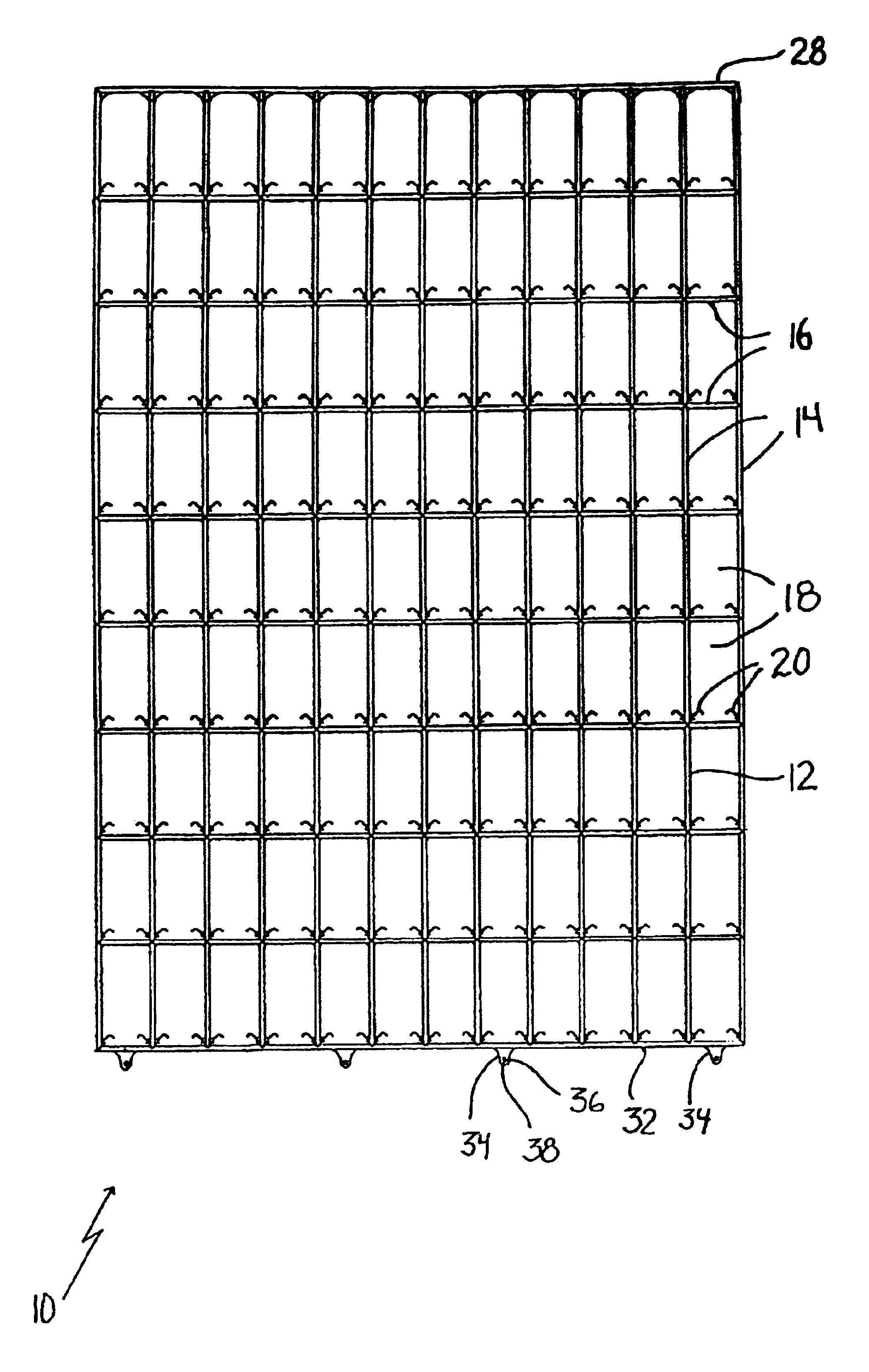
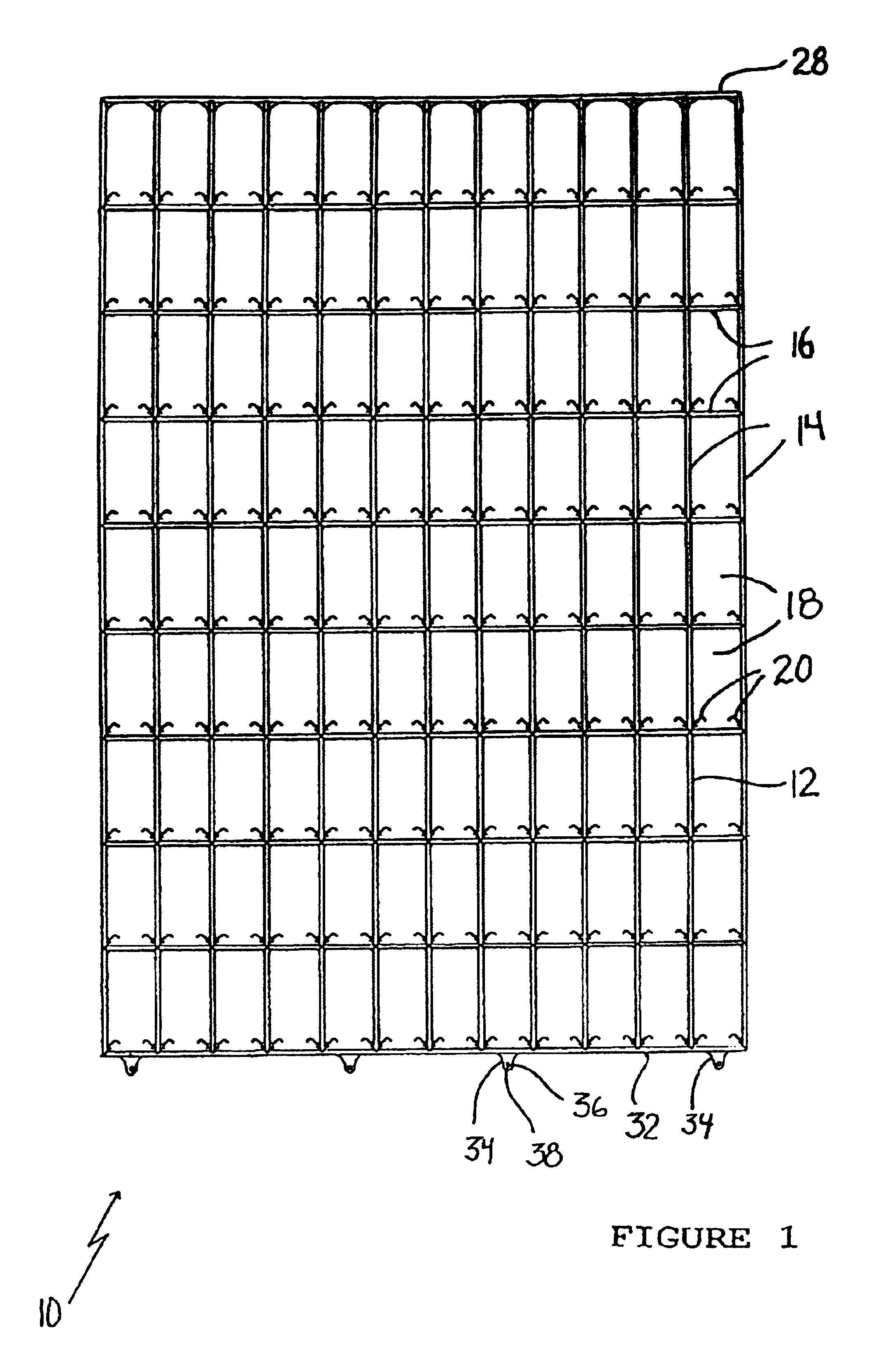
[0030]The preferred embodiment, a cooling tower support grid generally identified by reference numeral 10, will now be described with reference to FIGS. 1 through 9.

Structure and Relationship of Parts

[0031]Referring to FIG. 1, there is provided a cooling tower support grid 10 which includes a lattice frame 12 that has a first series of parallel bars 14 which intersect with a second series of parallel bars 16 to form a plurality of openings 18. Splash bar retaining clips 20 are integrally formed as part of lattice frame 12. Retaining clips 20 extend in opposed relation into each of openings 18. Each clip 20 extends from one of first series of bars 14 above and immediately adjacent to one of second series of bars 16. Referring to FIG. 7, each clip 20 has a lower retainer lip 22 and a resilient finger 24 which is angled upwardly and terminates in a downwardly bent portion 26.

[0032]Referring to FIG. 8, an upper peripheral edge 28 of lattice frame 12 has an integrally formed hook 30 wher...


PUM

PropertyMeasurementUnit
forceaaaaaaaaaa
surface areaaaaaaaaaaa
moldableaaaaaaaaaa

Abstract

A cooling tower support grid includes a lattice frame having a first series of bars which intersect a second series of bars to form a plurality of openings. Splash bar retaining clips are integrally formed as part of the lattice frame extending in opposed relation into each of the openings. This eliminates the need to handle separate retaining clips and, thereby, simplifies the installation process.

Description

[0001]This application is a Reissue of application Ser. No. 09 / 902,090, filed Jul. 10, 2001, and issued as U.S. Pat. No. 6,708,960 on Mar. 23, 2004.FIELD OF THE INVENTION[0002]The present invention relates to a cooling tower support grid for supporting splash bars.BACKGROUND OF THE INVENTION[0003]Cooling tower support grids are used to support splash bars which span across a cooling tower, so that the splash bars do not sag. The splash bars are offset both vertically and horizontally, so that water droplets falling vertically from near the top of the cooling tower will invariably strike one or more of the splash bars during descent. Large water droplets are broken into smaller water droplets upon striking one of the splash bars. As many water droplets strike the splash bars, a thin film of water tends to form on each splash bar which increases the surface area of water exposed to air.[0004]There is a tendency for splash bars to become dislodged due to impingement by water from above...

Claims


Application Information

Patent Timeline
Patent Type & Authority Patents(United States)
IPC IPC(8): B01F3/04F28F25/08
CPCF28F25/082F28F2275/085Y10S261/11
Inventor OLSON, LLOYDPAPADOPOULOS, NICOLAOS
Owner INT COOLING TOWER
Why Eureka
Try Eureka