
Multidirectional adaptable vertebral osteosyntsis device with reduced space requirement

a multi-directional adaptable, vertebral technology, applied in the field of spinal cord, can solve the problems of high system stress, no longer suitable, and performing an overall derotation movemen

Inactive Publication Date: 2011-08-16
MEDICREA TECH
View PDF15 Cites 15 Cited by
  • Summary
  • Abstract
  • Description
  • Claims
  • Application Information

AI Technical Summary

Benefits of technology

[0033]Thus, among other advantages, the device according to the invention allows the implant to be orientated in many directions using a system which requires a very small amount of space, and allows the bone-anchoring elements to be used either with rods or with plates.

Problems solved by technology

The adjusting of the pedicle-screws / rod pair may lead to very high stresses in the system before it is definitely locked.
Simply bending a rod in a single plane, bringing this rod gradually alongside or performing an overall derotation movement, is then no longer suitable.
Furthermore, reduction of an anterolisthesis requires the use of screws with a U, the arms of which are extended backwards, at the expense of requiring far more space.
Finally, in order not to stress the tightening elements during traction manoeuvres, use of a special-purpose reduction instrument is recommended but entails stressing the pedicle in tension; all of which cause preliminary weakening.2. The use of successive spacing pieces may prove tricky, increasing the number of manoeuvres.
The mechanically reliable nature of the immobilization assumes a perfect fit, although such fit is uncertain under operating conditions (firstly the constraints imposed by the process, the interposition of tissue, poor visual inspection, etc.) where the implant is embedded.
The absence of rotational locking between the anchoring part and the multi-axis ball also makes dismantling difficult and sometimes impossible.3. The special-purpose instruments required involve just as many unknowns which add to the operating time, requiring medical auxiliaries training, and finally make maintenance more involved.

Method used


Image

  • Multidirectional adaptable vertebral osteosyntsis device with reduced space requirement
  • Multidirectional adaptable vertebral osteosyntsis device with reduced space requirement
  • Multidirectional adaptable vertebral osteosyntsis device with reduced space requirement

Examples


Embodiment Construction

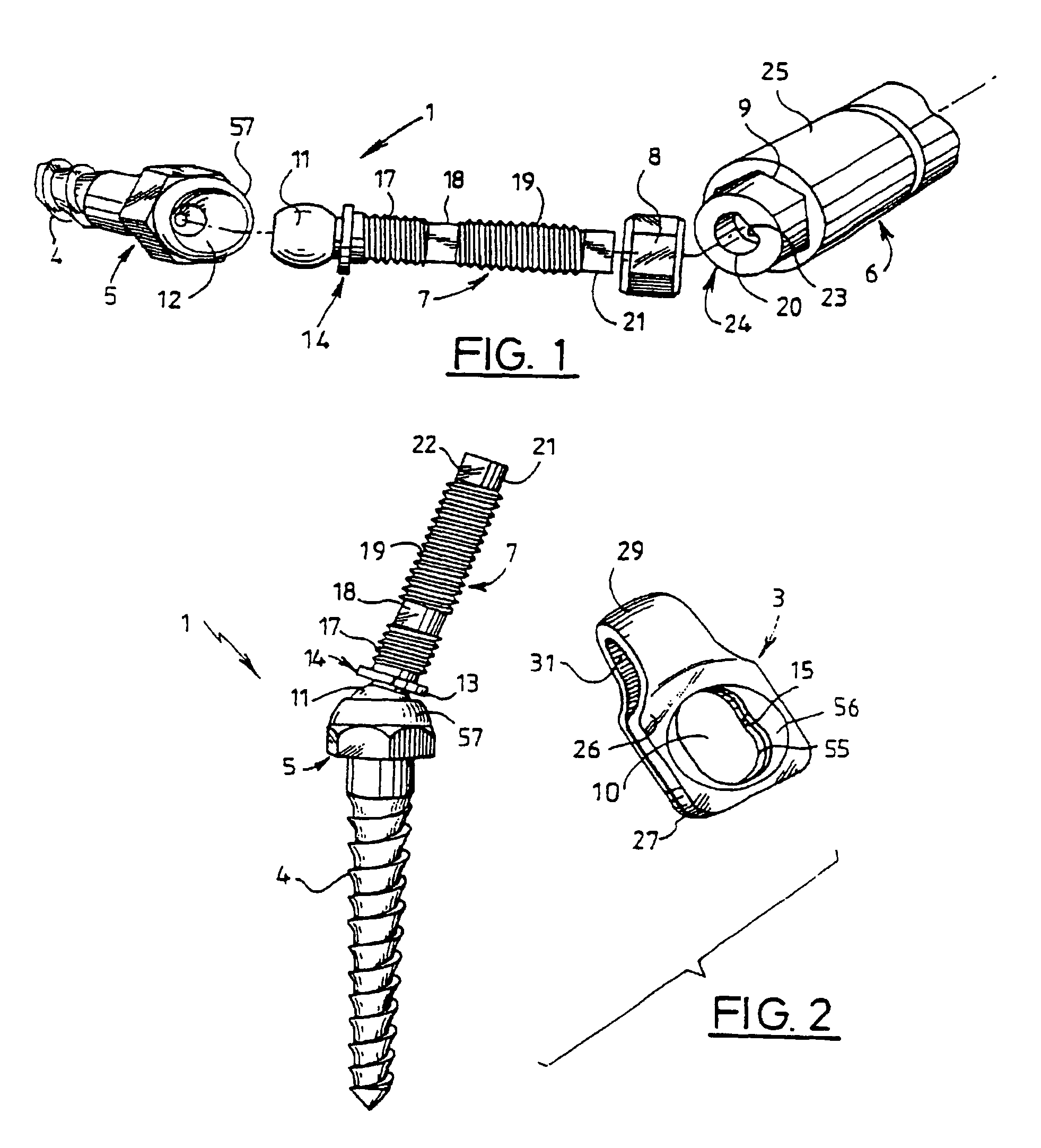
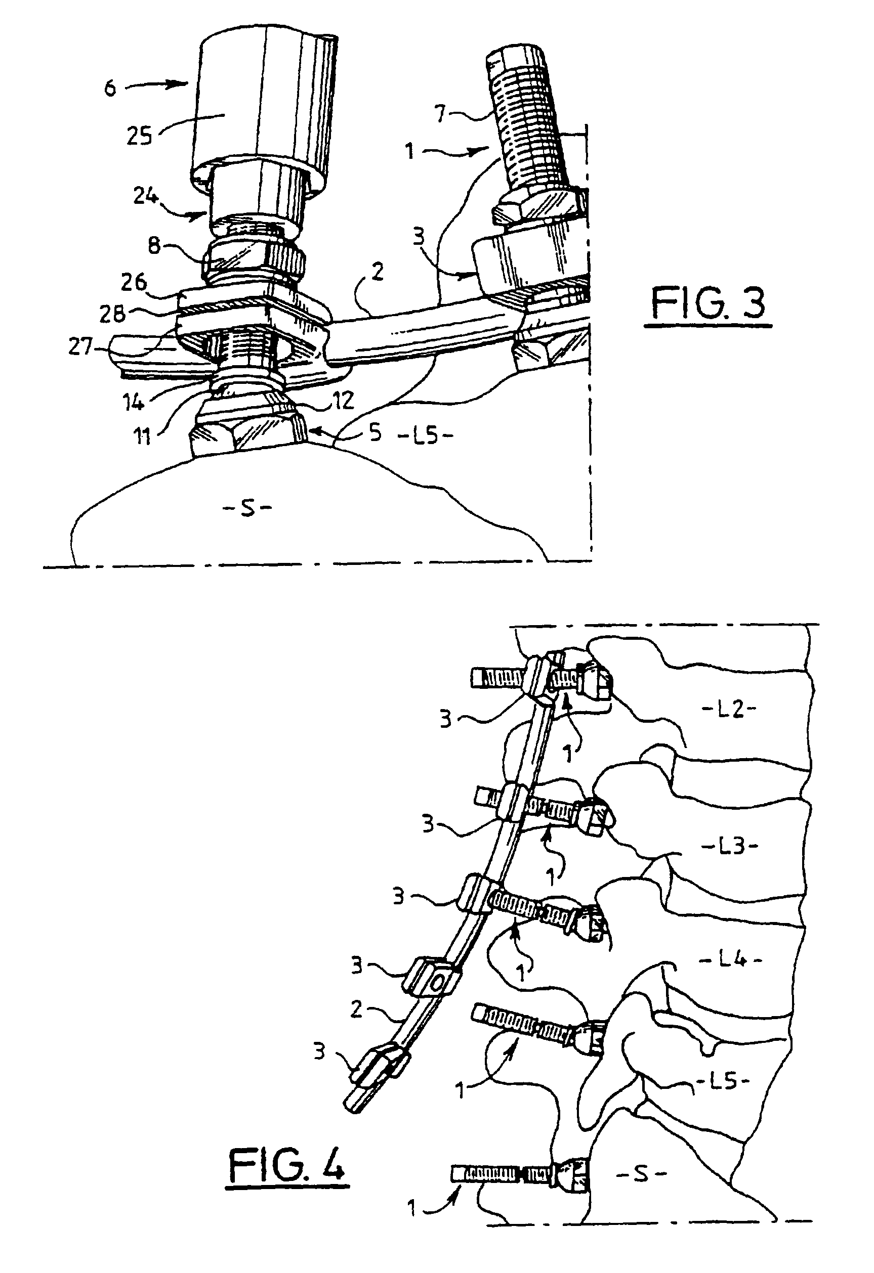
[0054]The spinal osteosynthesis device illustrated in FIGS. 1 to 6 comprises several bone-anchoring elements, consisting, in the example described, of elements 1 for anchoring into the bone of the respective vertebrae, a member for longitudinally connecting the bone-anchoring elements 1, which member consists of a vertebral rod 2, and shackles 3 for connecting the bone-anchoring elements 1 to the vertebral rods 2, there being one shackle 3 per bone-anchoring element 1. Each element 1 comprises a tapered bone-anchoring threaded shank 4, a head 5 for grasping with a screwing tool 6, a mechanical threaded shank 7 extending the head 5. The device is supplemented by a nut 8 which can be screwed onto the threaded shank 7 to lock together the connecting shackle 3, the vertebral rod 2 and the corresponding bone-anchoring element 1.

[0055]The head 5 for grasping has a shape which can cooperate with a screwing tool 6, for example a hexagonal outline as depicted, designed to cooperate with a fe...


PUM


Abstract

A vertebral osteosynthesis device includes at least two bone anchoring elements (1) in the vertebral bone structures respectively (S, L5.), a longitudinal linking member (2) between the bone anchoring elements, and connector links (3) between the bone anchoring elements and said linking members. Each bone anchoring element includes a bond fixing part (4), a head (5) to be gripped by a screwing device, a threaded shaft (7) extending the grip head, and a clamping element (8) to be screwed on said shaft to lock together the connector link, the longitudinal linking member and the corresponding bone anchoring element; the threaded shaft (7) is provided at its end with a hinge ball joint (11) in a housing (12) of the grip head (5), enabling a multidirectional adjustment of the shaft (7) and a positioning of the connector link (3) adapted to the vertebral segment configuration (S, L5, . . . Lw) receiving the bone anchoring elements.

Description

FIELD OF THE INVENTION[0001]The subject of the present invention is a spinal, particularly dorso-lumbar, osteosynthesis device.[0002]More specifically, the invention is aimed at a device of the type comprising at least two bone-anchoring elements for anchoring into bone structures of the spine, a member for longitudinally connecting the bone-anchoring elements, and shackles for connecting the bone-anchoring elements and the members for connecting the screws; each bone-anchoring element comprises an anchor for anchoring into the bone, a head for grasping by a screwing tool, a threaded shank extending the head for grasping and a tightening element which can be mounted on this shank to lock together the connector, the longitudinal connecting member and the corresponding bone-anchoring element.BACKGROUND OF THE INVENTION[0003]Multivertebral, particularly dorso-lumbar, osteosynthesis combines the use of screws or hooks connected together by plates or rods.[0004]The use of plates with app...

Claims


Application Information

Patent Timeline
IPC IPC(8): A61F5/00A61B17/58A61B17/70A61B17/80
CPCA61B17/7007A61B17/701A61B17/7014A61B17/7037A61B17/7041A61B17/7047A61B17/7052A61B17/8061
Inventor TAYLORVILLARET, BERNARD
Owner MEDICREA TECH
Learn More