Miniature BNC connector

a technology of bnc connector and bnc connector, which is applied in the direction of coupling device connection, coupling device details, coupling/disassembly parts, etc., can solve the problems of impeded further increase in connection densities, mechanical footprint of standard bnc connector, and lack of certain advantages, so as to achieve small and compact

Inactive Publication Date: 2011-11-15
M&G USA +1
View PDF59 Cites 9 Cited by
  • Summary
  • Abstract
  • Description
  • Claims
  • Application Information

AI Technical Summary

Benefits of technology

[0018]The connector assembly of the present invention is smaller and more compact than previous connector assemblies, particularly full-size BNC mating connector pairs. The connector assembly of the present invention achieves an improvement of approximately 30 percent more interconnects per given area than full-size BNC mating connector pairs, while including all of the attributes of the standard full-size BNC c

Problems solved by technology

Increased market demand for telephone lines (for voice, fax and data traffic) has caused additional crowding in telephone company central offices.
However, the mechanical footprint of the standard BNC connector hinders further increases in connection densities.
Connectors, such as the SMB connector, with smaller footprints might be used, but they lack certain advantages (e.g., the bayonet locking feature and field crimpability) of BNC connectors, which have become an industr

Method used


Image

  • Miniature BNC connector
  • Miniature BNC connector
  • Miniature BNC connector

Examples


Embodiment Construction

Overview

[0030]While specific configurations and arrangements are discussed, it should be understood that this is done for illustrative purposes only. A person skilled in the relevant art will recognize that other configurations and arrangements can be used without departing from the spirit and scope of the invention. It will be apparent to a person skilled in the relevant art that this invention can also be employed in a variety of other devices and applications.

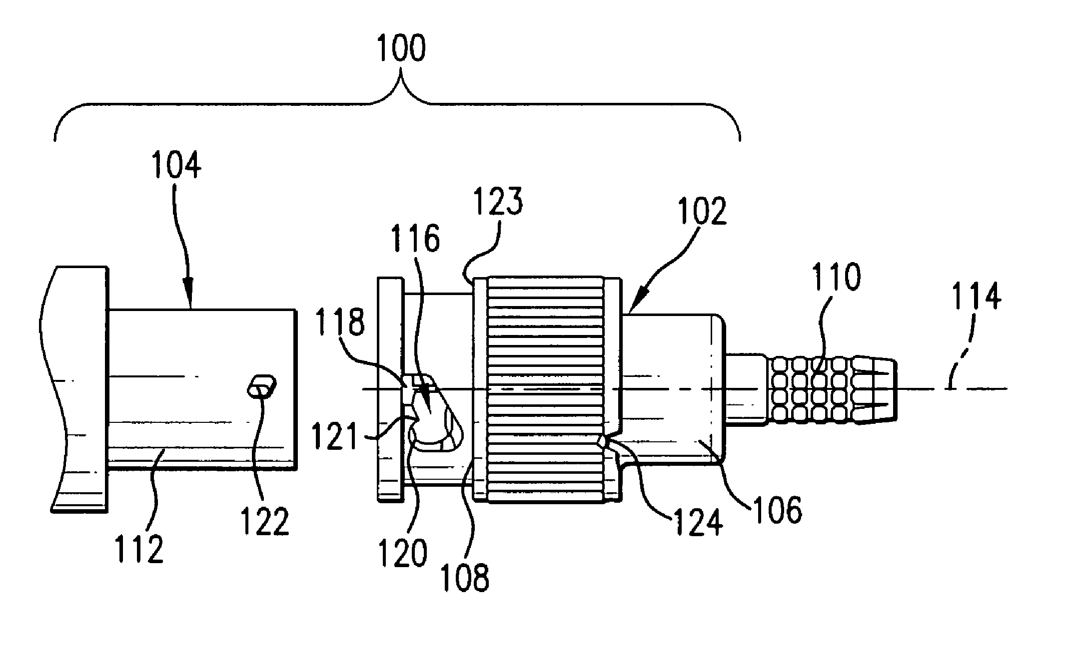
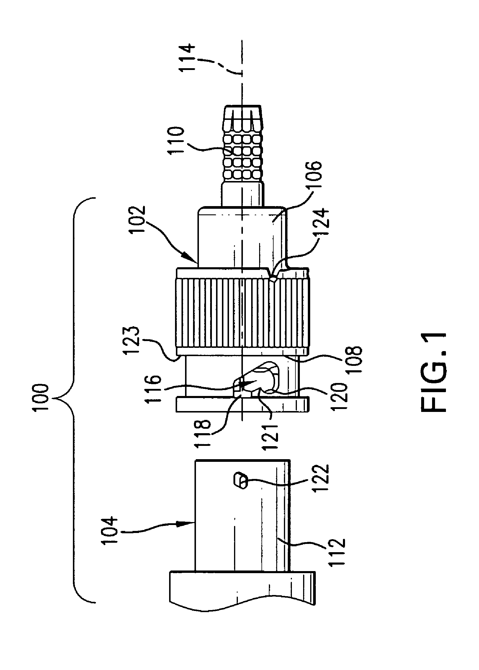
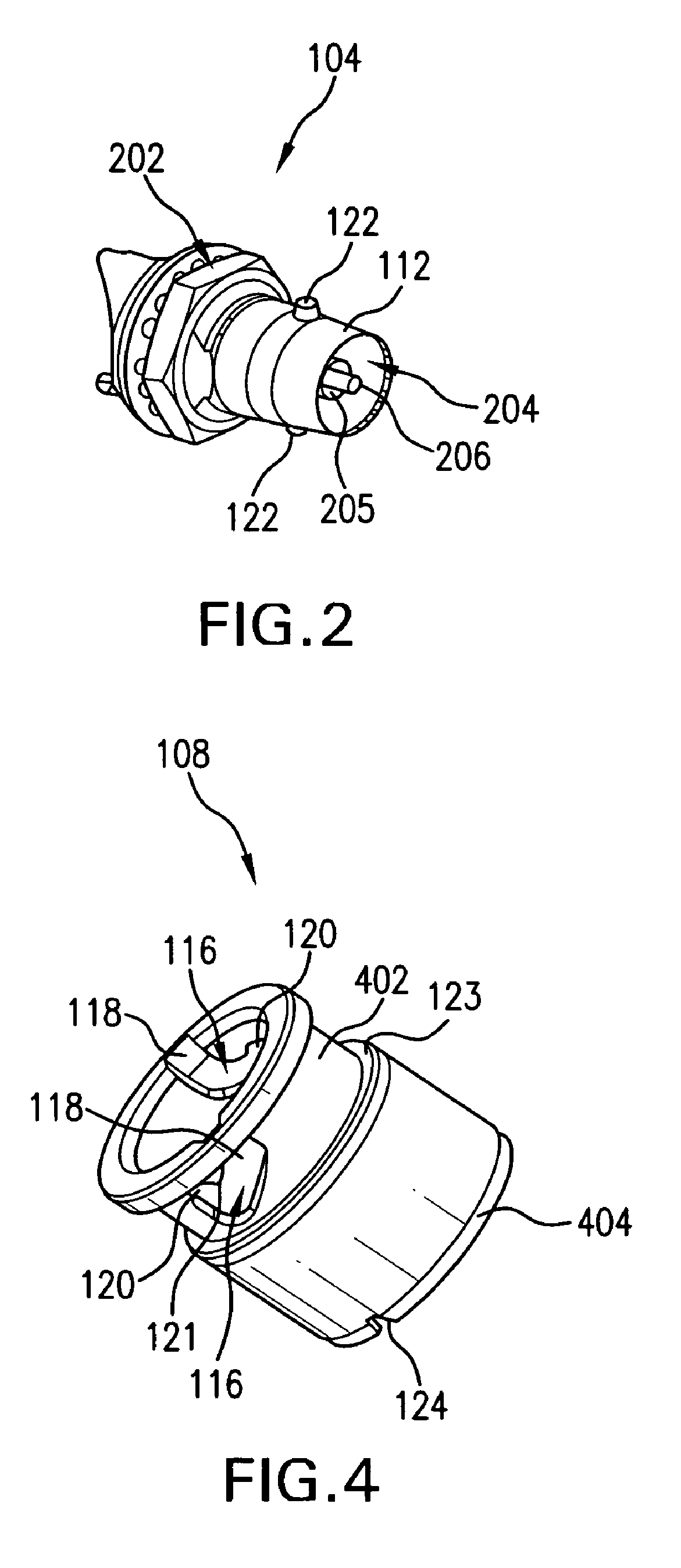
[0031]When working in tight areas, it is sometimes hard to determine if a plug and jack-side of a connector are fully mated or engaged. Embodiments of the present invention provide a jack-side connector having a first securing device and a plug-side connector having a sleeve rotatably coupled thereto. The sleeve has a second securing device that is complementary to the first securing device and an indicator located on an edge of the sleeve. The indicator is contrasted against a characteristic (e.g., color, material, etc.) of...


PUM


Abstract

A miniature BNC connector assembly having reduced dimensions includes a plug-side connector configured for engagement with a jack-side connector to form an electrical connection. The plug-side connector includes a plug-side connector body and a bayonet sleeve rotatably connected to the connector body. The bayonet sleeve has an outer diameter not greater than approximately half an inch.

Description

CROSS REFERENCE TO RELATED APPLICATIONS[0001]This application is a continuation of U.S. application Ser. No. 10 / 436,351, filed May 13, 2003 now U.S. Pat No. 6,921,283 (that published as U.S. Pub. Pat. App. No. 2004-0038584-A1 on Feb. 26, 2004), which is incorporated by reference herein in its entirety.[0002]U.S. application Ser. No. 10 / 436,351 is a continuation-in-part of U.S. application Ser. No. 09 / 938,857 filed Aug. 27, 2001 (that issued as U.S. Pat. No. 6,561,841 on May 13, 2002), which is incorporated by reference herein in its entirety.[0003]U.S. application Ser. No. 10 / 436,351 is also a continuation-in-part of U.S. application Ser. No. 10 / 038,581, filed Jan. 8, 2002 (that published as U.S. Pub. Pat. application No. 2003-0129870-A1 on Jul. 10, 2003, now abandoned), which is incorporated by reference herein in its entirety.BACKGROUND OF THE INVENTION[0004]1. Field of the Invention[0005]The present invention relates generally to the field of electrical connectors. In particular,...

Claims


Application Information

Patent Timeline
IPC IPC(8): H01R13/52H01R13/625H01R13/641H01R13/646
CPCH01R13/625H01R13/641H01R24/40H01R2103/00
Inventor NORWOOD, JOE D.HIDALGO, ANTHONY
Owner M&G USA
Why Eureka
Try Eureka