Display devices having rounded corner backlight unit

a backlight unit and display device technology, applied in waveguides, identification means, instruments, etc., can solve the problems of poor quality lcd and damage to the lamp, and achieve the effect of reducing or eliminating light concentration

Inactive Publication Date: 2013-05-21
SAMSUNG DISPLAY CO LTD
View PDF17 Cites 0 Cited by
  • Summary
  • Abstract
  • Description
  • Claims
  • Application Information

AI Technical Summary

Benefits of technology

[0011]It is another object of the present invention to provide light guide panels and backlight units which can reduce light concentration in a light guide projection thereof.
[0012]These and other objects are provided, according to the present invention, by a backlight unit for a display device having a mold frame including a groove and having a light guide panel including a light projection mounted in the groove, wherein the mold frame groove and light guide projection each include at least one rounded corner. The rounded corner can prevent light from being concentrated at the corners of the projecting portion.
[0014]A light source is also mounted on the mold frame in spaced apart relation from the light guide panel. In this configuration, the mold frame groove and the light guide panel both include a first corner and a second corner which is remote from the light source relative to the first corner. The first corner is preferably angled and the second corner is preferably rounded. Thus, the first angled corner may effectively prevent the light guide panel from damaging the light source. The second corner may be used to reduce light concentration from the light source and thereby improve the quality of the LCD. In other embodiments, the groove and the light guide projection are both free of all sharp angles. In other embodiments, both the first and second corners may be rounded.
[0016]Accordingly, the present invention can prevent the light source from being destroyed during movement of the LCD, by fitting the light guide projection into grooves in the mold frame. The present invention also can reduce or eliminate light concentration at portions of the LCD by rounding the corners of the projection and light guide panel.

Problems solved by technology

Therefore, it is possible to damage the lamp when the LCD module is shaken or external forces are imparted to the LCD module.
The concentrated light may result in a poor quality LCD.

Method used


Image

  • Display devices having rounded corner backlight unit
  • Display devices having rounded corner backlight unit
  • Display devices having rounded corner backlight unit

Examples


Embodiment Construction

[0023]The present invention now will be described more fully hereinafter with reference to the accompanying drawings, in which preferred embodiments of the invention are shown. This invention may, however, be embodied in many different forms and should not be construed as limited to the embodiments set forth herein; rather, these embodiments are provided so that this disclosure will be thorough and complete, and will fully convey the scope of the invention to those skilled in the art. Like numbers refer to like elements throughout.

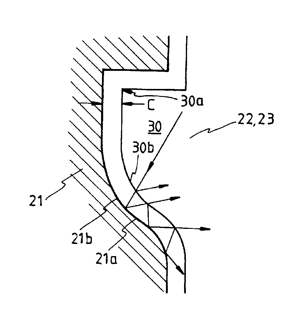
[0024]Referring now to FIG. 5, a mold frame 21 includes a concave groove 21a in its side so that light guide projection 30 of the light guide panel 22 fits into the groove 21a. The light guide projection 30 of the light guide panel 22 has at least one rounded corner 30b, and the groove 21a of the mold frame also has at least one rounded corner 21b corresponding to the shape of the projecting portion. A pair of diffuser sheets 23 (or a diffuser sheet and a ...


PUM

PropertyMeasurementUnit
concentrationaaaaaaaaaa
areaaaaaaaaaaa
distanceaaaaaaaaaa

Abstract

A backlight unit for a display device includes a mold frame and a light guide panel. The mold frame includes a groove having at least one rounded corner. The light guide panel is on the mold frame and includes a light guide projection in the groove, having at least one rounded corner corresponding to the at least one rounded corner of the mold frame groove.

Description

FIELD OF THE INVENTION[0001]This invention relates to display devices, and more particularly to backlight units for display devices.BACKGROUND OF THE INVENTION[0002]Display devices are widely used in many consumer and commercial applications. Display devices generally use light in order to display a visible image, especially in the dark. As is well known, display devices generally include active displays in which every picture element (pixel) emits light, and passive displays which use a source of light to project through the display panel. The source of light may be supplied by a backlight unit. Examples of active displays are cathode ray tubes (CRT) and light emitting diode (LED) displays. An example of a passive display is a liquid crystal display (LCD).[0003]A backlight unit of an LCD will now be described. Backlight units generally include a light source such as a lamp, a reflecting sheet, a light guide panel and a diffusing sheet. The backlight unit and the display panel are g...

Claims


Application Information

Patent Timeline
Patent Type & Authority Patents(United States)
IPC IPC(8): F21V7/04G02F1/1335G01D11/28G09F9/00F21V8/00G02F1/13357
CPCG01D11/28G02B6/0088G02F1/133615Y10S362/812Y10S385/901G09F9/00
Inventor LEE, IK-SOO
Owner SAMSUNG DISPLAY CO LTD
Why Eureka
Try Eureka