
A kind of backlight device and its installation process

An installation process and backlight technology, applied in optics, nonlinear optics, instruments, etc., can solve the problems of changing the optical path, reducing the utilization rate of light energy, and losing the effect of improving the brightness of the backlight, so as to improve the uniformity and brightness , Reduce the effect of light concentration

Active Publication Date: 2020-07-03
深圳市利航电子有限公司
View PDF6 Cites 0 Cited by
  • Summary
  • Abstract
  • Description
  • Claims
  • Application Information

AI Technical Summary

Problems solved by technology

[0004] The above-mentioned existing technical solutions have the following defects: part of the light emitted by the LED light source is directed towards the side of the film, at this time part of the light is irradiated on the film frame under the refraction of the film side wall, and the other part of the light is reflected back into the film and its optical path It is still parallel to the surface of the film and cannot change the optical path through the reflective film, so it has no effect on the brightness of the backlight, resulting in a decrease in the utilization of light energy

Method used


Image

  • A kind of backlight device and its installation process
  • A kind of backlight device and its installation process
  • A kind of backlight device and its installation process

Examples


Embodiment Construction

[0044] The present invention will be described in further detail below in conjunction with the accompanying drawings.

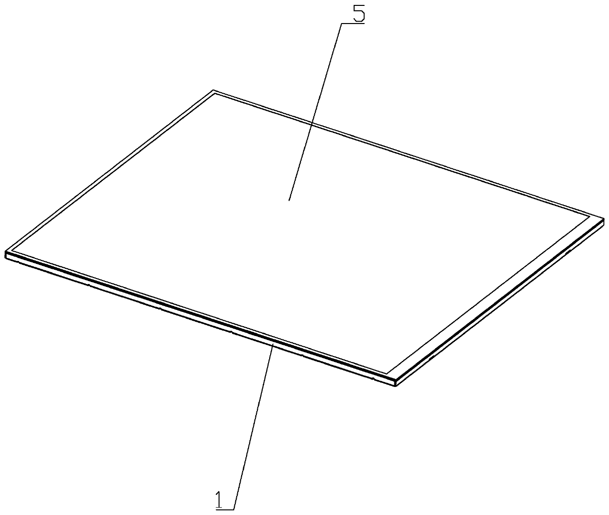
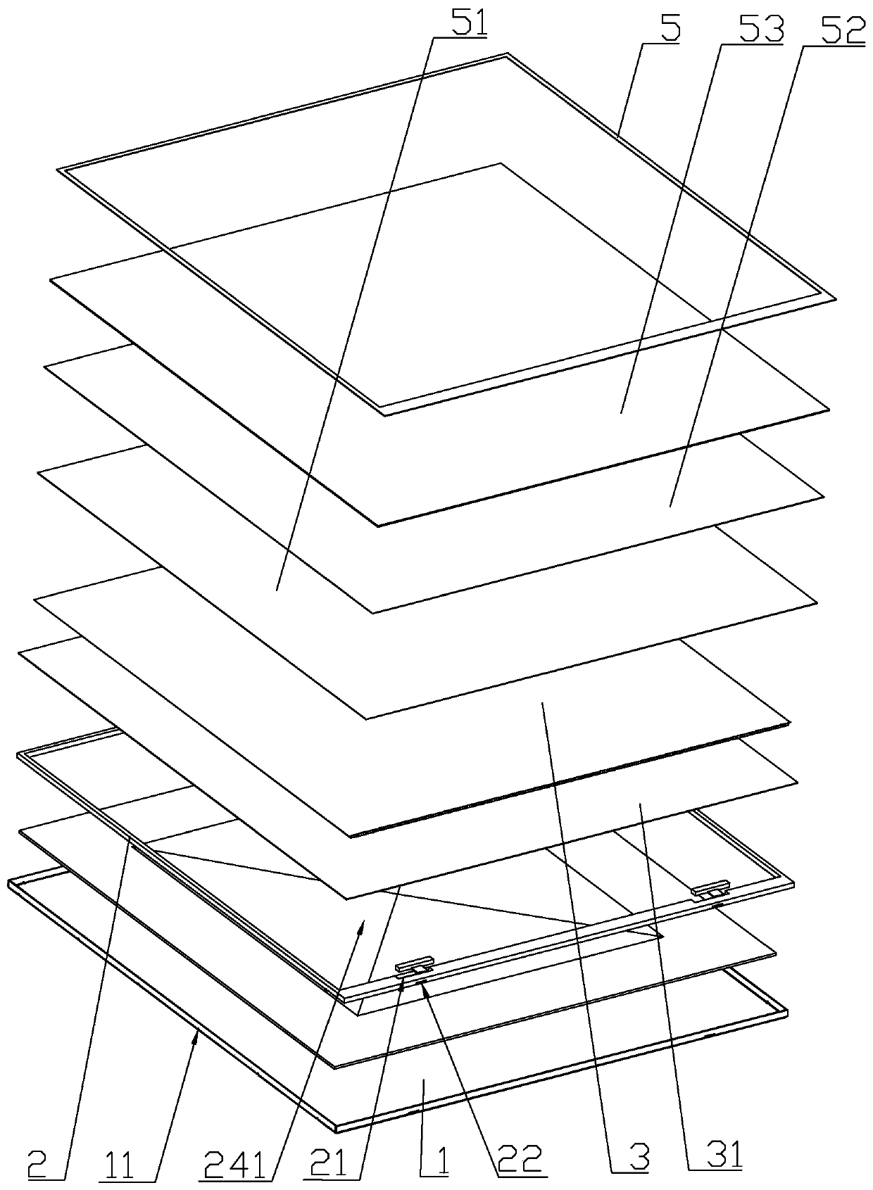
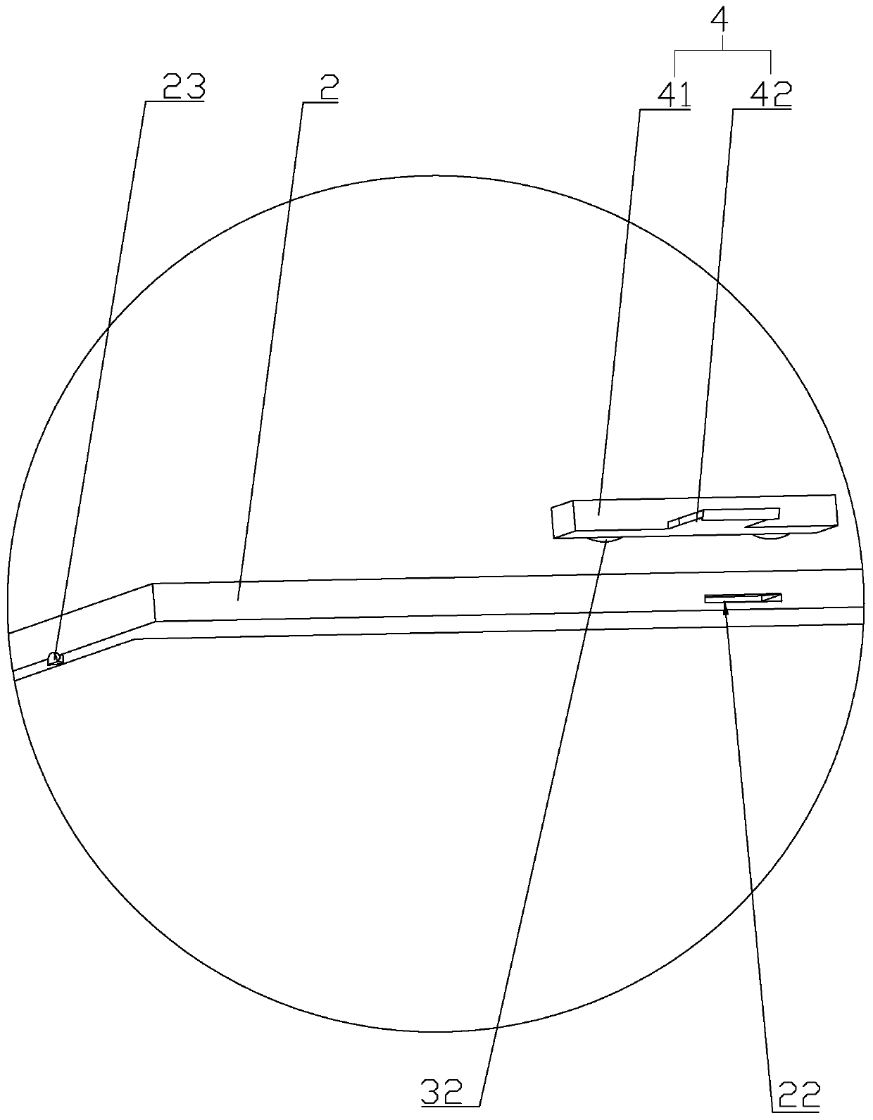
[0045] refer to figure 1 , figure 2 , is a backlight device disclosed in the present invention, including a support sheet 1 for placing a reflective film 31 and a support frame 2 plugged with a film 3 , the edge of the support frame 2 abuts against the inner side wall of the support sheet 1 . The supporting sheet 1 is made of a square aluminum alloy sheet, and the four corners of the supporting sheet 1 are provided with right-angle grooves so that the supporting sheet 1 is cross-shaped. Afterwards, the line connecting the turning points of the right-angled grooves is selected as the reference line, and a plurality of through holes 11 are formed at uniform intervals along the reference line by a punching machine, and the plurality of through holes 11 are distributed along the circumferential edge of the support sheet 1 .

[0046] Then fold the adjacent two ...


PUM


Abstract

The invention relates to a backlight device and an installation technology thereof and also relates to the illumination equipment technology field. A support sheet used for placing a reflection film and a support frame which is plugged and cooperated with a film are included. An edge of the support frame abuts against an inner side wall of the support sheet, the edge of the film is provided with achamfered surface which is inclined towards a diffusion film, one side of the chamfered surface is superposed with a top edge of the film, and the chamfered surface is coated with a silver powder. Aneffect of increasing a luminous energy utilization rate is achieved.

Description

technical field [0001] The invention relates to the technical field of lighting equipment, in particular to a backlight source device and an installation process thereof. Background technique [0002] At present, the backlight (BackLight) is a light source located behind the liquid crystal display (LCD), and its luminous effect will directly affect the visual effect of the liquid crystal display module (LCM). The liquid crystal display itself does not emit light, and it displays graphics or characters as a result of its light modulation. It is widely used in touch screens, backlights, LCD / LCM, mobile phones, tablet computers, GPS, solar cells and other industries. [0003] The Chinese utility model with the notification number CN208222196U discloses a backlight device based on ring-attached glue. The backlight device includes: a plastic frame for fixing the backlight components; The film; the LED light source arranged on the upper side of the film frame and the bottom of th...

Claims


Application Information

Patent Timeline
Patent Type & Authority Patents(China)
IPC IPC(8): G02F1/13357
CPCG02F1/133603G02F1/133605G02F1/133606G02F1/133608
Inventor 黄生妮
Owner 深圳市利航电子有限公司
Learn More