Filtering apparatus and filter element

a filter element and filtering technology, applied in the field of filtering apparatus, can solve the problems of high production cost, unintentional off of the filter element, and less known solution, and achieve the effects of low production cost, simple structure design, and reliable connection

Active Publication Date: 2016-07-26
HYDAC FILTERTECHNIK GMBH
View PDF44 Cites 2 Cited by
  • Summary
  • Abstract
  • Description
  • Claims
  • Application Information

AI Technical Summary

Benefits of technology

[0007]Objects of the present invention are to provide a filtering apparatus and filter element therefor guaranteeing a reliable connection of the filter element within the filter housing by the holding means, having an especially simple, structural design resulting in low production costs and easy installation, and having good sealing action and resistance to corrosive media.
[0008]These objects are basically achieved by a filter device and a filter element where the sealing means has at least one sealing edge or sealing surface. The sealing edge or sealing surface is located in the axial direction parallel to the longitudinal axis, and seals under the influence of the pressure applied thereto by the holding means. It is then possible to abandon conventional O-rings which extend between the filter element and the filter head as the housing cover in the radial direction. Nor does the sealing means have to be made from rubber materials, as in the known solutions, and is accordingly suitable for any type of fluid to be filtered, even corrosive media. Depending on the medium to be filtered in the form of a fluid, the sealing means can be stipulated to be suitably resistant in terms of its material selection. Damage to the sealing means in the various installation processes can also for the most part be avoided, even if the filter element were to be placed obliquely on parts of the holding means so as to cause tilting. In this way, long lasting operation can be ensured by the sealing means.

Problems solved by technology

The comparatively complex design of the known holding means leads to high production costs.
Also, the known solution is less easy to install, in that the filter element can slip unintentionally off the connecting branch or can tilt at this location when put in place.
This installation difficulty leads to an adverse effect on the sealing action of the sealing means.
This known sealing means with an O-ring is not suited for all fluid media, for example, not for all hydraulic liquids, poorly flammable liquids, corrosive media and for special biodegradable liquids.
Depending on the chemical structure of the respective medium, a long-lasting sealing function cannot be ensured.
In this respect, installation problems (slippage, tilting) can also arise when the filter element has to be pushed onto the support mandrel, for example, when the filter is being replaced on site, with the disadvantageous consequence that the sealing action of the sealing means is adversely affected.
Although, in addition the support mandrel as a component of the holding means in the longitudinal axial direction parallel to the longitudinal axis of the filter element on its lower base part in a receiving groove has another gasket which is not subject to any further mechanical stress, in any case, as described above the sealing action of the sealing means between the filter element and support mandrel as a housing part is adversely affected.
For example, no other components which are formed optionally as aftermarket elements could endanger the safe use of the filter device.
In this respect the above described disadvantages also apply to the known filter device according to that European patent.

Method used


Image

  • Filtering apparatus and filter element
  • Filtering apparatus and filter element
  • Filtering apparatus and filter element

Examples


Embodiment Construction

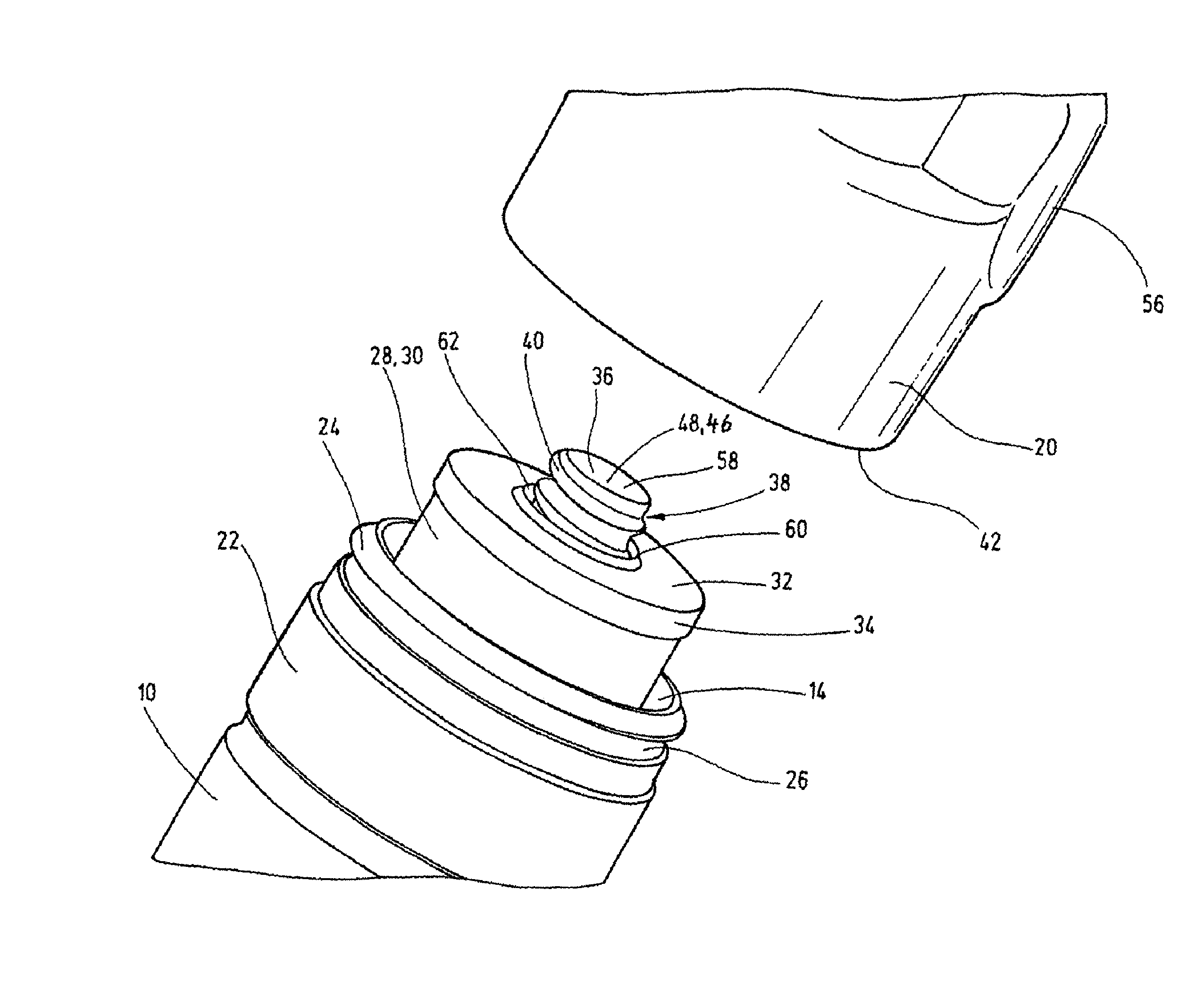
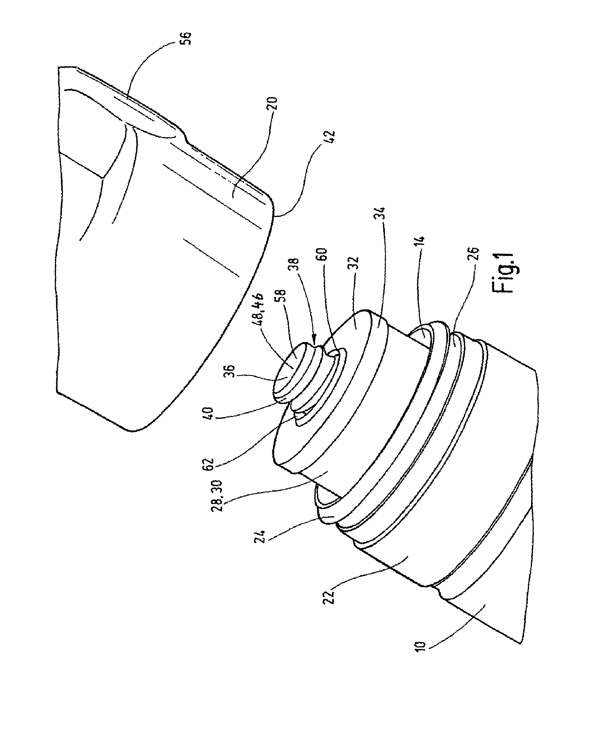
[0018]A filter housing 10 is in the form or shape of a cup rotationally symmetrical in its outline to the longitudinal axis 12, and has one open top end 14 and a closed bottom (not shown). On the top end 14, a peripheral catch groove 16 in the form of a snap connection can be engaged by a catch overlap of the cover part or housing cover 20 of the filter housing 10, when the cover part 20 is placed on the top end 14 of the filter housing 10 by a rotary or snap motion. This snap and catch connection for the housing cover 20 with the filter housing 10 is shown especially in FIG. 3. Alternatively, as shown in FIG. 1, instead of a catch groove 16, a peripheral elevation 22 can be provided with an external threaded segment (not shown) to screw on the housing cover 20 by an internal threaded segment (not shown). In both cases, as shown in FIG. 1, in the direction of the top end 14, a projecting, peripheral sealing lug 24 at the top borders a sealing channel 26 which can house a sealing mea...


PUM

PropertyMeasurementUnit
pressureaaaaaaaaaa
transition pointaaaaaaaaaa
shapeaaaaaaaaaa

Abstract

A filtering apparatus includes a pot-type filter housing (10), a filter element (28) accommodated in the housing, a holding mechanism (38) disposed in the filter housing (10) to removably fix the filter element along its longitudinal axis, and a sealing device (60) that seals between a lid (20) of the filter housing (10) and the filter element (28). The holding mechanism (38) is provided with cooperating holding elements embodied on the interior face of the filter housing (10) as well as on the filter element (28). The filtering apparatus dispenses with the need for O-seals that are known in prior art and extend in a radial direction between the filter element and the filter head as a housing lid because the sealing device (60) encompasses at least one sealing edge (62) or sealing surface placed parallel to the longitudinal axis in a radial direction and seals under the effect of the pressure applied it by the holding mechanism (38). The invention further relates to a filter element that is to be used in such filtering apparatus.

Description

FIELD OF THE INVENTION[0001]The present invention relates to a filtering apparatus having a cup-like filter housing, a filter element held therein, and a holding means located in the filter housing for detachable fixing of the filter element along its longitudinal axis and having holding elements which interact with one another and which are formed on the inside of the filter housing and on the filter element. A sealing means effects sealing between the housing cover of the filter housing and the filter element. The present invention furthermore relates to a filter element designed for the filter device.BACKGROUND OF THE INVENTION[0002]Filter devices for holding filter elements are readily available commercially in a host of embodiments. A not insignificant portion of production costs in these filter devices is for making the holding means for detachable fixing of the filter element within the housing and for the sealing means for sealing the interior of the filter element relative ...

Claims


Application Information

Patent Timeline
Patent Type & Authority Patents(United States)
IPC IPC(8): B01D35/30B01D27/07B01D29/11B01D29/96
CPCB01D35/30B01D2201/291B01D2201/302B01D2201/304B01D2201/305B01D2201/4092B01D29/114B01D29/96
Inventor MAURER, PATRICKSANN, NORBERT
Owner HYDAC FILTERTECHNIK GMBH
Why Eureka
Try Eureka