
Self-experiencing expansion pile shoe and immersed tube poured pile re-piling method
A technology of pile shoes and mold tubes, applied in sheet pile walls, foundation structure engineering, construction, etc., can solve problems such as reducing the bearing capacity of single piles, dispersing the formation of pile bodies, and destroying the plastic shape of the foundation, so as to improve construction efficiency and engineering quality, increase the bearing capacity of single piles, and reduce the effect of soil extrusion
- Summary
- Abstract
- Description
- Claims
- Application Information
AI Technical Summary
Problems solved by technology
Method used
Image

Examples
Embodiment Construction
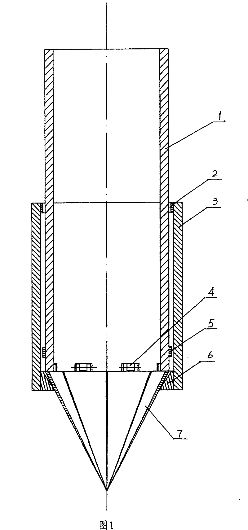
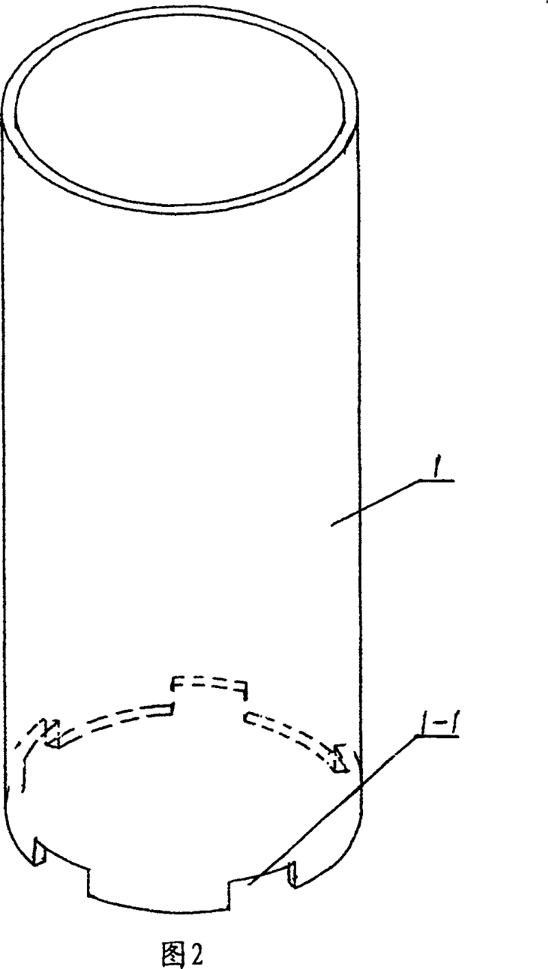
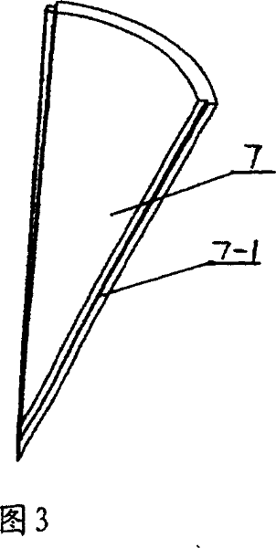
[0012] Referring to Figure 1, Figure 2, Figure 3, the pile shoe includes a mold tube 2 and a steel sleeve 3. There are several notches 1-1 on the periphery of the bottom end of the mold tube 1, and the hinge 4 is welded inside, and the movable sleeve of each hinge is welded. A piece of arc triangular leaflet 7 is connected, so that each leaflet can swing radially, and a snap ring 5 is welded above the gap 1-1 at the lower end of the outer wall of the mold tube 1 . The lower end of the mold tube 1 is covered with a steel sleeve 3, and the upper and lower edges of the inner wall of the steel sleeve 3 are welded and connected to the upper positioning ring 2 and the lower positioning ring 6, wherein the inner circle of the lower positioning ring 6 has a large upper and a lower small into an inclined plane, which is combined with the movable vane 7. Constitutes a tapered guiding effect. When the mold tube 1 sinks, the outer diameter of the vane 7 and the bottom of the lower positio...
PUM
 Abstract
Description
Claims
Application Information