
Pump device

A technology of pump devices and balance devices, which is applied in the direction of pump devices, pumps, components of pumping devices for elastic fluids, etc., can solve problems such as insufficiency, and achieve the effect of improving efficiency

Inactive Publication Date: 2007-09-26
HITACHI LTD
View PDF7 Cites 0 Cited by
  • Summary
  • Abstract
  • Description
  • Claims
  • Application Information

AI Technical Summary

Problems solved by technology

But this is only about the impellers further back than the one that takes out the lubricating fluid, still not enough

Method used


Image

  • Pump device
  • Pump device
  • Pump device

Examples


Embodiment Construction

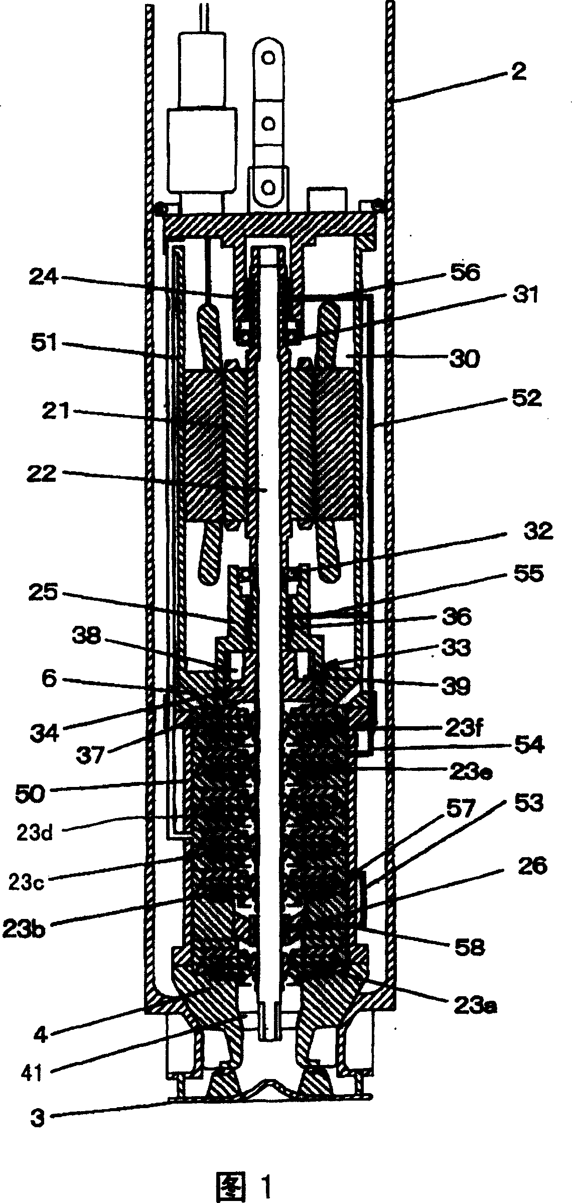
[0033] Hereinafter, the best mode for carrying out the present invention will be described. FIG. 1 shows the structure of a submerged pump device for liquefied gas according to one embodiment. This pump device is common to the conventional pump device described in terms of its usage and basic structure. Therefore, in the following description, the above description is used for the mode of use, the same reference numerals as those in FIG. 6 are assigned to components common to conventional pump devices, and their descriptions are omitted by referring to the above description.

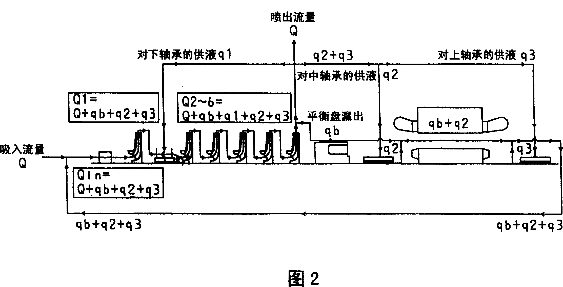
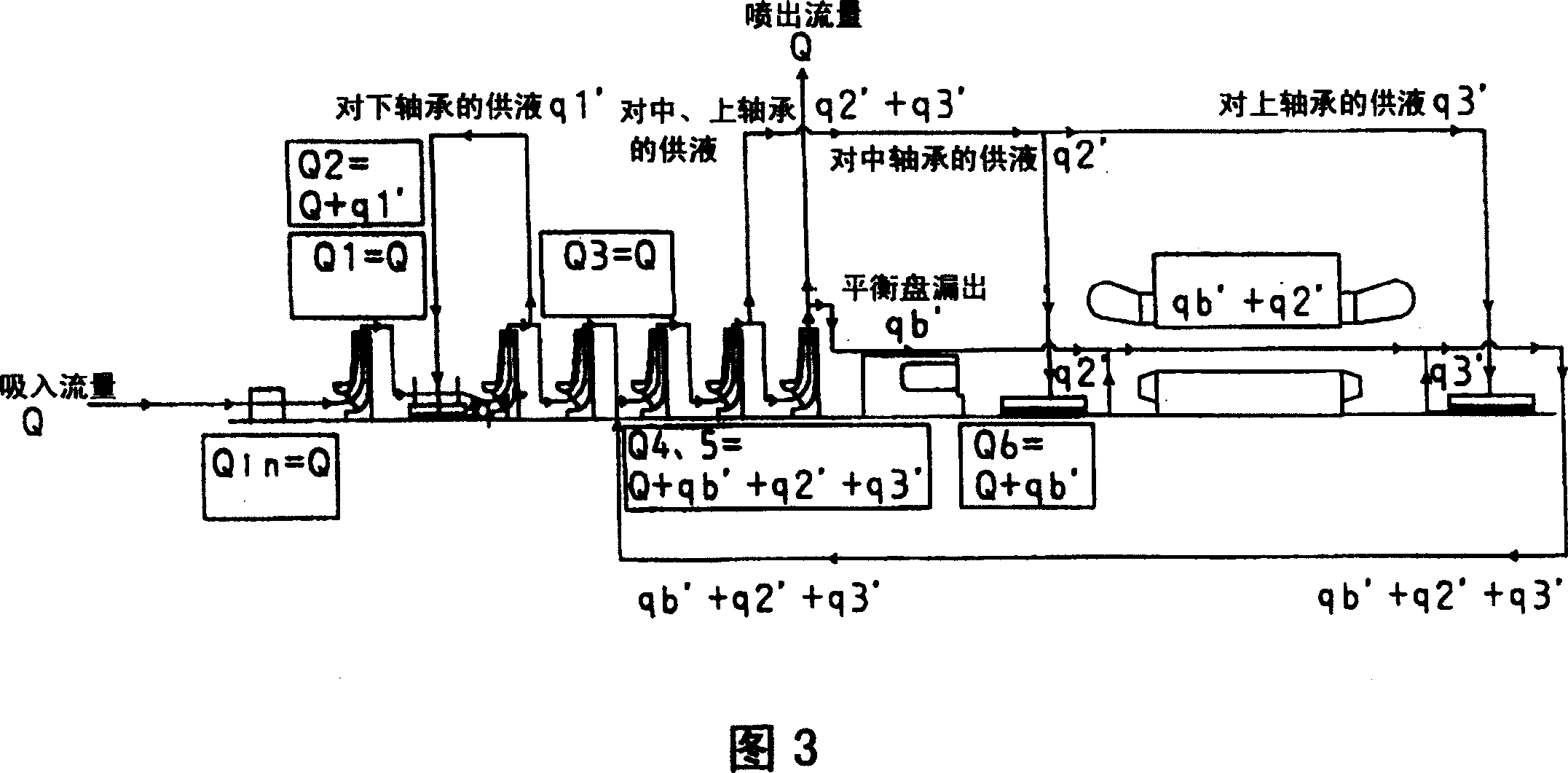
[0034] The pump device 50 shown in FIG. 1 is characterized by a structure for maintaining the pressure of the motor chamber 30 and a structure for supplying lubricating fluid to the hydrostatic bearings 24 to 26 . First, the pressure holding structure of the motor chamber will be described. In the motor chamber 30 , the liquid discharged from the upper hydrostatic bearing 24 and the middle hydrostatic ...


PUM


Abstract

A pump device for pressurizing a fluid to be fed, comprises: a rotary shaft (22), a bearing (24, 25, 26) including a bearing surface adapted to face to the rotary shaft so that the rotary shaft is supported on the bearing surface in a rotatable manner, and an impeller (23) fixed to the rotary shaft to be rotatable with the rotary shaft so that the fluid is pressurized by a rotation of the impeller.

Description

technical field [0001] The present invention relates to a pump device, in particular to a submersible pump device suitable for use in a submerged state in a storage tank when pumping liquefied natural gas such as liquefied natural gas up from the storage tank. Background technique [0002] A submersible pump device for liquefied gas generally includes a shaft thrust balancer for reducing the thrust load applied to the bearing. In addition, in submersible pumps for liquefied gas, hydrostatic bearings are used in order to prolong the life of the bearings, and the lubricating fluid of the hydrostatic bearings adopts a self-lubricating structure using liquid boosted by the impeller. As such a pump device, for example, examples disclosed in Patent Documents 1 and 2 are known. [0003] Fig. 5 and Fig. 6 show typical usage examples and structural examples of these conventional pump devices. Figure 5 shows the extraction device for the liquefied gas liquid in the liquefied gas sto...

Claims


Application Information

Patent Timeline
Patent Type & Authority Patents(China)
IPC IPC(8): F04D7/02F04D13/08F04D15/00F04D1/08F04D13/00F04D29/04
CPCF04D29/0416F04D1/063F04D29/061F04D29/041F04D13/08F04D29/007F04D29/044F04D29/046F05D2210/11Y10S415/00Y10S417/00
Inventor 福地贵树桥本泰司天野和雄
Owner HITACHI LTD
Learn More