Cooling units and cabinets for cabinets

A cooling device and cabinet technology, applied in the computer field, can solve the problems of poor heat dissipation efficiency of cabinets and computer rooms, too long cold air circulation path, etc., and achieve the effect of shortening the circulation path and improving heat dissipation efficiency

Active Publication Date: 2018-05-22
BEIJING BAIDU NETCOM SCI & TECH CO LTD
View PDF13 Cites 0 Cited by
  • Summary
  • Abstract
  • Description
  • Claims
  • Application Information

AI Technical Summary

Problems solved by technology

[0004] However, due to the above-mentioned cooling method, the cooling efficiency of the cabinet and the machine room is poor due to the long circulation path of the cold air.

Method used


Image

  • Cooling units and cabinets for cabinets
  • Cooling units and cabinets for cabinets
  • Cooling units and cabinets for cabinets

Examples


Embodiment Construction

[0016] The application will be further described in detail below in conjunction with the accompanying drawings and embodiments. It should be understood that the specific embodiments described here are only used to explain related inventions, rather than to limit the invention. It should also be noted that, for the convenience of description, only the parts related to the related invention are shown in the drawings.

[0017] It should be noted that, in the case of no conflict, the embodiments in the present application and the features in the embodiments can be combined with each other. The present application will be described in detail below with reference to the accompanying drawings and embodiments.

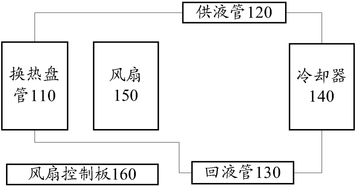
[0018] Please refer to figure 1 , figure 1 An exemplary structural diagram of a cooling device for a data center cabinet according to an embodiment of the present application is shown.

[0019] Such as figure 1 As shown, the cooling device of the data center cabinet may i...


PUM


Abstract

Disclosed are a cooling device for a machine cabinet, and a machine cabinet. The cooling device comprises: a heat exchange coil (110), arranged on the air-outlet side of a machine cabinet; a liquid supply pipe (120), in communication with an output opening of a cooler (140) and an input opening of the heat exchange coil (110), and used for conveying a coolant output by the cooler (140) to the heat exchange coil; a liquid return pipe (130), in communication with an output opening of the heat exchange coil (110) and an input opening of the cooler (140), and used for enabling the coolant output by the heat exchange coil (110) to flow back to the cooler (140); the cooler (140), used for cooling the coolant flowing back from the liquid return pipe and then outputting the cooled coolant to the liquid supply pipe (120); a fan (150), arranged on the air-outlet side of the heat exchange coil (110), and used for forming an air flow in an air outlet direction; and a fan control board (160), arranged in an air flow direction, and used for controlling the fan to act so as to form the air flow. The circulating path of cooling air is shortened, and the heat dissipation efficiency of the machine cabinet and the machine room is improved.

Description

technical field [0001] The present application relates to the field of computer technology, in particular to the field of computer data centers, especially to a cooling device and a cabinet for a cabinet. Background technique [0002] With the development of cloud computer data centers, it is necessary to use cooling methods to cool down the high-heat-generating equipment in the data center computer room. [0003] In the current cooling method, the air is first cooled by the fan coil in the machine room and then enters the cabinet through a long path, absorbs the heat generated by the cabinet, and then enters the fan coil through a long path, and uses a cooler or cooling tower to cool the fan coil tubes to dissipate the heat to the external environment. [0004] However, due to the above-mentioned cooling method, the circulation path of the cold air is too long, and the heat dissipation efficiency of the cabinet and the machine room is poor. Contents of the invention [...

Claims


Application Information

Patent Timeline
Patent Type & Authority Patents(China)
IPC IPC(8): H05K7/20
CPCH05K7/20
Inventor 谭显光陈国峰康盛
Owner BEIJING BAIDU NETCOM SCI & TECH CO LTD
Why Eureka
Try Eureka