
Comparision method for automatically comparing circuit design diagram with its modification conditions

A circuit design diagram and automatic comparison technology, which is applied in calculation, electrical digital data processing, special data processing applications, etc., can solve problems such as circuit scrapping, circuit board process damage, and easy omissions

Inactive Publication Date: 2007-09-26
INVENTEC CORP
View PDF5 Cites 0 Cited by
  • Summary
  • Abstract
  • Description
  • Claims
  • Application Information

AI Technical Summary

Problems solved by technology

After changing the placement of the original components, it is necessary to make a detailed comparison with the placement of the electronic components on the previous layer; the current operation method is mainly for the circuit designer to send the revised circuit design drawing to the layout Engineer, and attach a text description file of the differences between this version and the previous version, so that the layout engineer can know the differences between this version and the previous version. However, when there are more errors in the two layers or The position of the components is so close that it is difficult to identify them, and it is not only difficult to express the differences between them, but it is also easy to be overlooked in words. In addition, under the manufacturing process of the circuit board, due to these small defects, the circuit board will be damaged. If some components fail to work or lose function, the circuit will be completely scrapped. Usually, this kind of human negligence will cause great damage to the process of the circuit board, so it is very important to be able to correctly identify the defects on each circuit board.

Method used


Image

  • Comparision method for automatically comparing circuit design diagram with its modification conditions
  • Comparision method for automatically comparing circuit design diagram with its modification conditions

Examples


Embodiment Construction

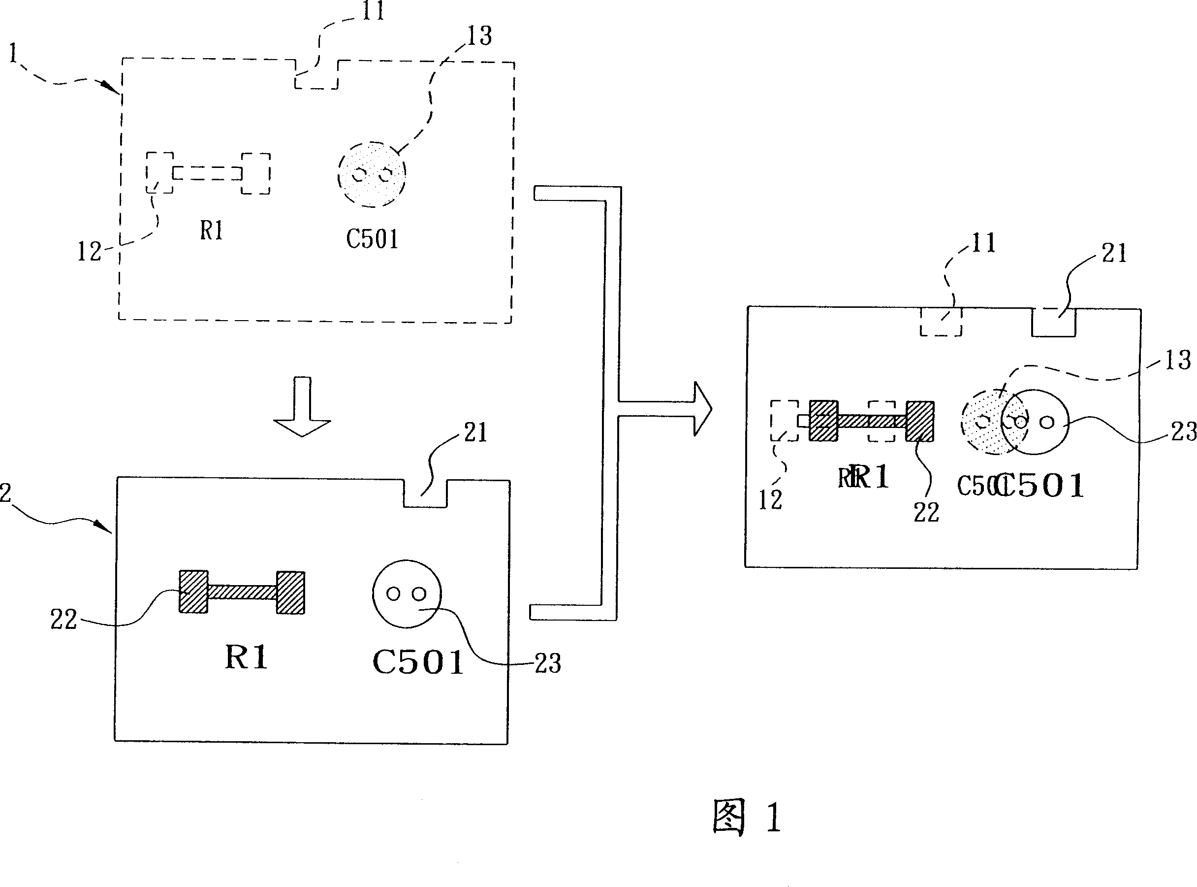
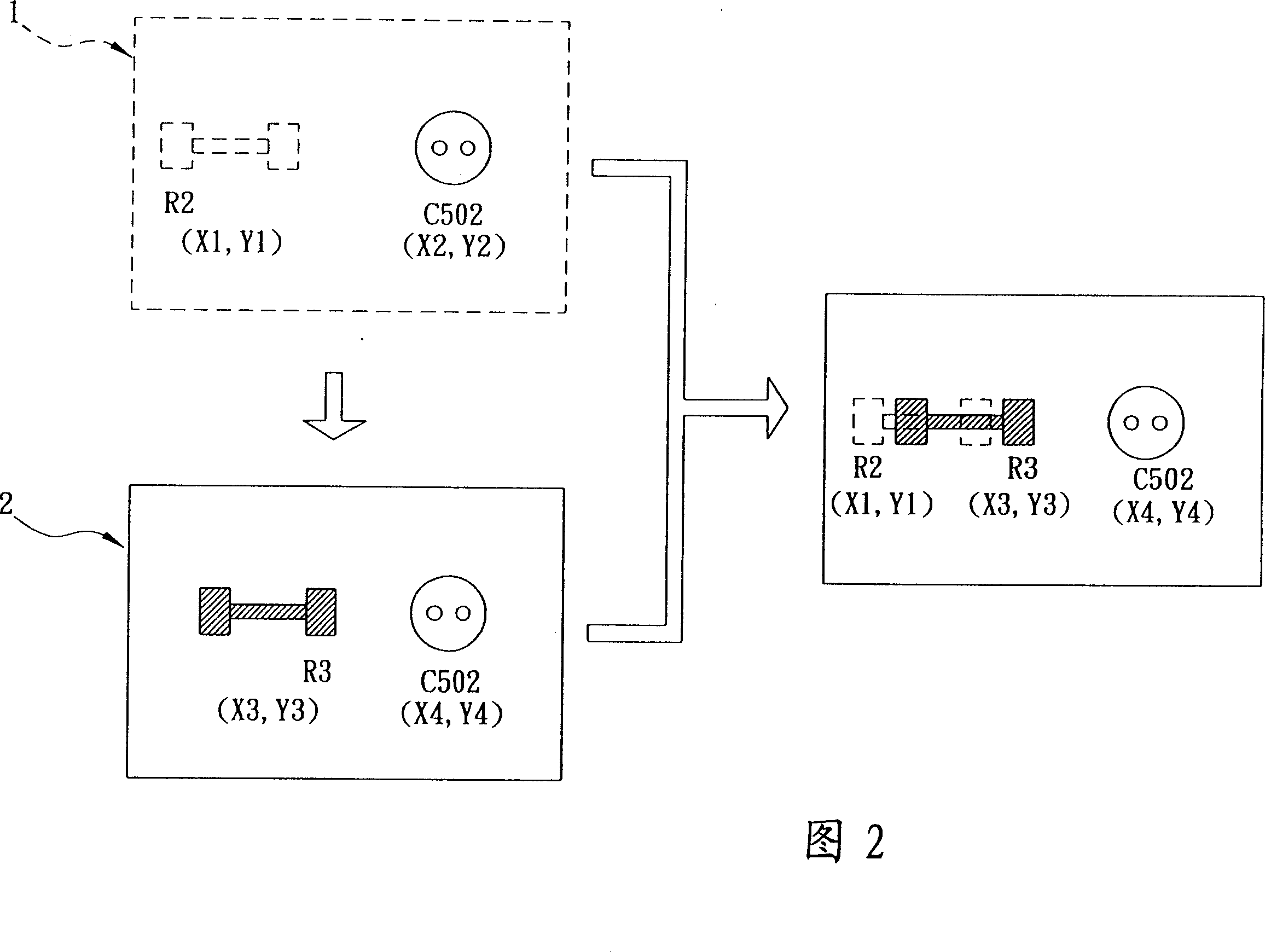
[0033] The present invention is a comparison method for automatically comparing the modification status of circuit design diagrams by software. Please refer to FIG. 1 . The first color layer (such as: yellow) is drawn, and when the components (such as resistor R1 and capacitor C501) on the previous version 1 of the circuit design diagram are modified or changed, the circuit design diagram is changed to the second color layer (such as: purple) to draw the latter version 2. Therefore, when you want to distinguish the difference between the previous version and the latter version 2 of the circuit design diagram, you can use an automatic comparison program on the computer to compare the circuit design The latter version 2 of the figure is superimposed on the previous version 1 for comparison, and the difference after the comparison is displayed on the display screen. In this way, the difference in color can be displayed and distinguished on the display screen of the computer. Diff...


PUM


Abstract

The invention is a comparing method of using software to compare the modifying conditions of circuit design chart, as using a computer to draw a circuit design chart, making the previous version of the circuit design chart drawn by the first chromatograph and the back version drawn by the second chromatograph, and on the point of differentiating the difference between the previous and back versions of the circuit design chart, able to use an automatic comparison program to superpose the back version on the previous version, because the back version has been changed or modified so that the back version cannot be completely covered on the previous version, mainly displaying the circuit design chart after comparison on the computer screen in the color of the second chromatograph adopted by the back version, but displaying the changed or modified component or design by the first and second chromatographs, respectively, and thus using different colors to differentiate the difference between the previous and back versions of the circuit design chart.

Description

technical field [0001] The invention relates to a method for comparing the differences before and after modification of circuit design diagrams, in particular to a comparison method for automatically comparing the modification status of circuit design diagrams with software. technical background [0002] With the development of science and technology, all kinds of small and exquisite electronic parts are widely used in the electronics industry. The early circuits and components were relatively simple, and only the copper foil on the substrate was used as the connection of the circuit, which made it easier to make. Recently, transistor circuits, IC The advent of circuits, computer systems, etc., has made the circuit design more and more complex and more refined. Double-layer panels or more layer panels have emerged as the times require. Multi-layer panels are a circuit board that contains three layers. Or more than three layers of electrical circuits or components. [0003] ...

Claims


Application Information

Patent Timeline
IPC IPC(8): G06F17/50
Inventor 郑永健
Owner INVENTEC CORP
Learn More