Supercharge Your Innovation With Domain-Expert AI Agents!

Block brake

A brake and block type technology, applied in the direction of drum brakes, brake types, brake components, etc., to achieve the effect of simple structure and sensitive braking

Inactive Publication Date: 2007-10-03
石家庄市奇力科技有限公司
View PDF9 Cites 0 Cited by
  • Summary
  • Abstract
  • Description
  • Claims
  • Application Information

AI Technical Summary

Problems solved by technology

The disadvantage of this brake is that when the electromagnet is energized and working, the armature of the electromagnet and the forehead iron are tightly attracted together, and its braking torque is determined by the buffer spring. Once the preload force of the brake and the distance between the two brake shoes After the adjustment, the braking torque of the brake is a constant, and the braking process is in place in one step, and it is impossible to produce a smooth braking process.

Method used


Image

  • Block brake
  • Block brake

Examples


Embodiment Construction

[0009] specific implementation

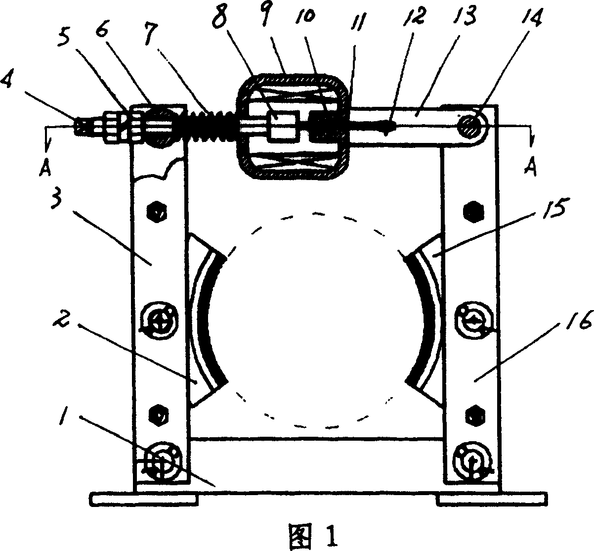
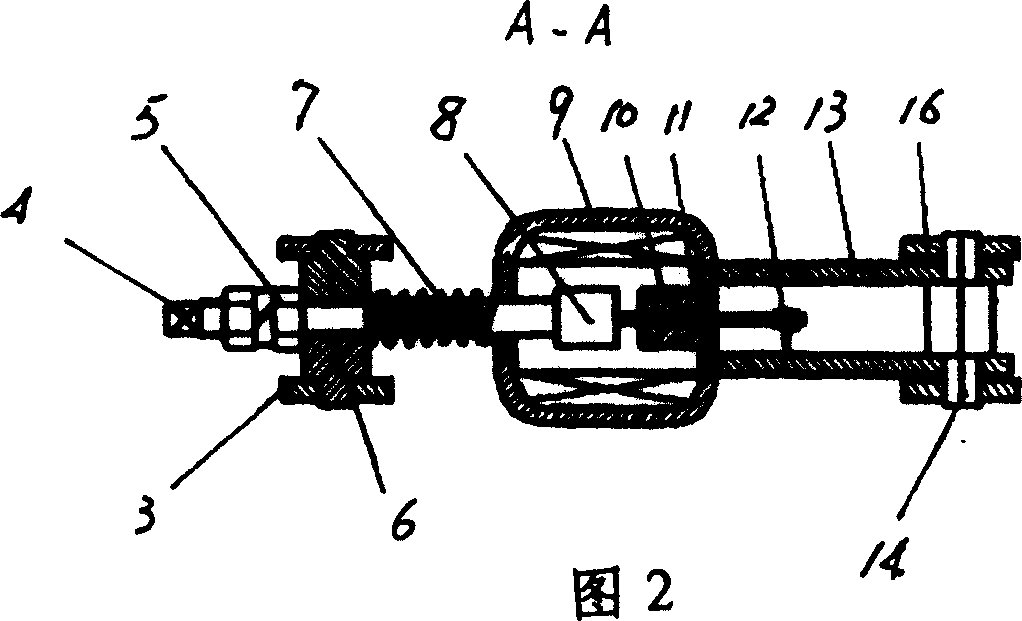
[0010] As can be seen from the embodiment shown in Figures 1 and 2, it includes a base 1, left and right brake arms 3, 16 respectively hinged to the base 1, a pair of brake shoes 2 respectively hinged to the left and right brake arms , 15, brake pull rod 4, brake electromagnet 9, brake release spring 7; brake pull rod 4 is directly connected with the armature 8 of brake electromagnet 9; it is characterized in that brake pull rod 4 passes through left pin shaft 6 and left system The boom 3 is hinged, that is, the brake rod 4 passes through the hole of the left pin shaft 6 and is limited by the nut 5 threadedly connected with the brake rod 4 on the left side of the left pin shaft 6; the brake release spring 7 is set on the left pin shaft 6 and the brake rod 4 between the housing of the brake electromagnet 9; the brake electromagnet 9 is hinged with the right brake arm 16 through the right pin 14 through a pair of mounting p...


PUM


Abstract

The invention relates to a block brake, comprising base, left and right brake arms connected with the base, a pair of brake shoes respectively connected with the left and right brake arms, brake pull rod, brake electromagnet, and brake release spring, where the brake pull rod is connected directly with an armature iron of the brake electromagnet, and characterized in that: the brake pull rod is hinged with the left brake arm through shaft pin, i.e. after the brake pull rod passes through a hole of the shaft pin, it is limited by a nut screwed with it and located on the left side of the shaft pin; the brake release spring is jacketed on the brake pull rod between the shaft pin and a brake electromagnet casing; the brake electromagnet is hinged with the right brake arm through a pair of installation plates fixed on the right side of the brake electromagnet casing with shaft pin; as the brake electromagnet is electrified to work, the armature iron is kept a gap apart from yoke block. It has simple structure and brake sensitivity.

Description

technical field [0001] The invention relates to a block brake, which belongs to a normally open block brake and is suitable for braking a crane. Background technique [0002] Chinese patent CN2345772Y discloses a "normally open electromagnet block brake", which includes front and rear brake arms, bases, brake shoes, brake levers, electromagnets, brake release springs, armature pull rods of electromagnets and system The moving lever is directly connected; the brake lever is connected to the rear brake arm through a buffer spring. The disadvantage of this brake is that when the electromagnet is energized, the armature of the electromagnet and the forehead iron are tightly attracted together, and the braking torque is determined by the buffer spring. Once the preload of the brake and the distance between the two brake shoes After the adjustment, the braking torque of the brake is a constant, and the braking process is in place in one step, and it is i...

Claims


Application Information

Patent Timeline
Patent Type & Authority Patents(China)
IPC IPC(8): F16D65/21F16D49/16F16D65/18
Inventor 张旗张利张家政
Owner 石家庄市奇力科技有限公司
Features
  • R&D
  • Intellectual Property
  • Life Sciences
  • Materials
  • Tech Scout
  • Unparalleled Data Quality
  • Higher Quality Content
  • 60% Fewer Hallucinations
Learn More