Drum vent

A technology of air vents and drums, which is applied in the field of air vent devices, and can solve problems such as loss of air vent performance, condensation of chemicals, and drying out

Inactive Publication Date: 2007-10-17
ENTEGRIS INC
View PDF5 Cites 3 Cited by
  • Summary
  • Abstract
  • Description
  • Claims
  • Application Information

AI Technical Summary

Problems solved by technology

[0010] However, with thinner films that are guarded, there is a problem that chemicals can "hang" on the guard structure and potentially accumulate around the film
These chemicals may condense or dry out, causing the vent to fail
Also, the relatively rigid structure of the protective plate required to adequately protect and constrain the membrane may in some cases result in a loss of vent performance

Method used


Image

  • Drum vent
  • Drum vent
  • Drum vent

Examples


Embodiment Construction

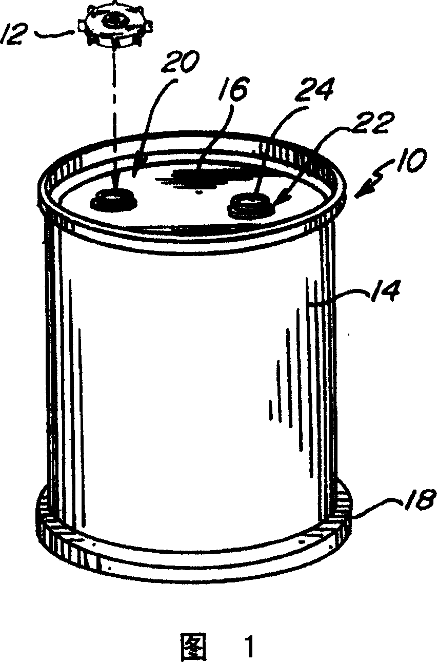
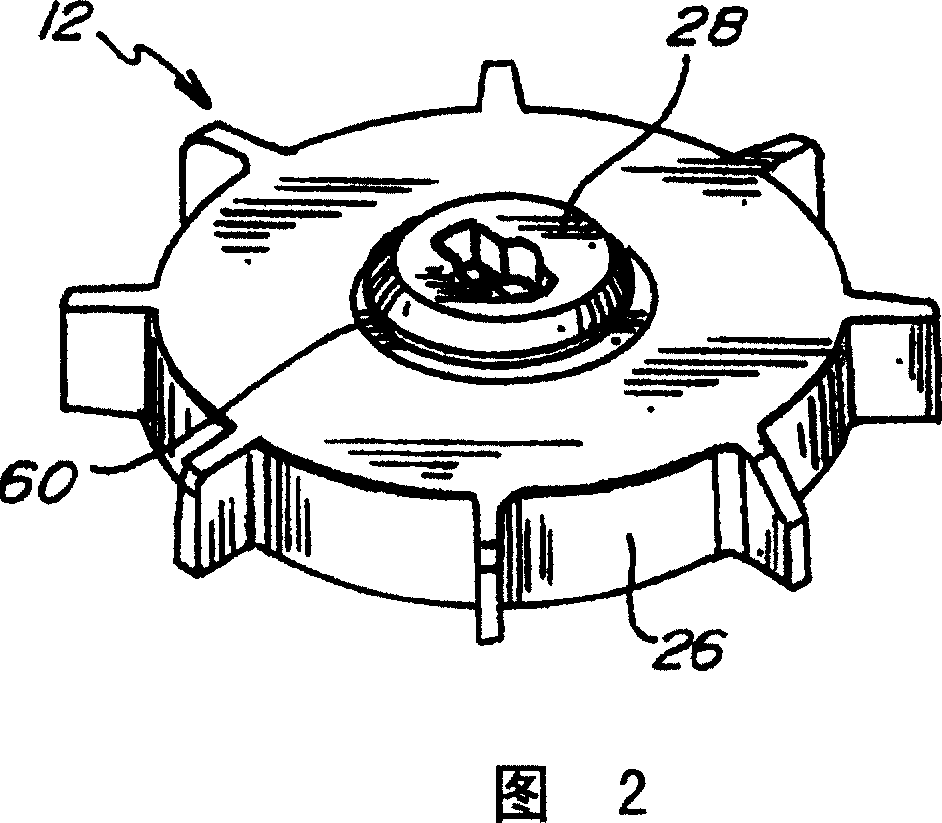
[0023] Referring to Figures 1 and 2, there is shown a drum shell 10 and vent plug 12 in accordance with the present invention. FIG. 1 shows in perspective a blow molded drum 10 generally comprising a cylindrical wall portion 14 , a top structure 16 and a bottom structure 18 . The top structure 16 includes a first barrel opening 20 and a second barrel opening 22 . The second barrel hole is closed with a standard plug 24 which sealingly engages in the second barrel hole 22 . The vent plug 12 is sealingly engaged within the first barrel bore 20 . The first and second barrel bores 20 , 22 generally have internal threads that threadably engage external threads on the vent plug 12 and the standard plug 24 . It should be appreciated, however, that any alternative means known to those of ordinary skill in the art may be used to engage the bore plug 12 and bung 24 within the barrel bores 20, 22.

[0024] FIG. 2 shows a perspective view of the vent plug 12 . The vent plug 12 general...


PUM


Abstract

A venting device for a drum. The venting device includes a body having a pair of opposing sides and defining a plurality of vent passages. The vent passages extend through the body and each an opening at each of the pair of opposing sides. The vent passages are spaced apart and arranged around a center portion of the body. A membrane structure is positioned so as to cover the openings of the vent passages on one of the pair of opposing sides of the body. The membrane structure is sealingly affixed to the body portion in a sealing band surrounding the openings of the vent passages. A portion of the membrane structure is further affixed to the center portion of the body. A protective structure may be attached to the body and positioned over the membrane structure.

Description

[0001] This application claims the benefit of U.S. Provisional Patent Application Serial No. 60 / 422,433, filed October 30, 2002, and entitled "Vent Plug," which is hereby incorporated by reference in its entirety. technical field [0002] The present invention relates to venting of drums, and more particularly to a venting device for drums. Background technique [0003] Drums, barrels, and other containers are commonly used to store, transport, and dispense chemicals and industrial fluids. An example of such a drum is disclosed in US Patent No. 6,045,000 held by the proprietor of the present invention and incorporated herein by reference in its entirety. In some industries, such as semiconductor processing, the contained fluids may be highly volatile and may contain vapors or gases which will build up pressure within the container until vented. An example of such a fluid is hydrogen peroxide, which will contain oxygen. Also, like hydrogen peroxide, these fluids may be toxi...

Claims


Application Information

Patent Timeline
Patent Type & Authority Patents(China)
IPC IPC(8): B65D51/16B65D85/84
CPCB65D51/1644B65D85/84B65D7/045B65D25/40B65D51/16
Inventor D·梅恩克
Owner ENTEGRIS INC
Why Eureka
Try Eureka