
Electric permanent-magnet following clamp for delivery and its uses

A traveling fixture, electro-permanent magnet technology, applied in clamping, circuit, magnetic materials and other directions, can solve the problems of inability to ensure the accurate lateral positioning of the workpiece, the position of the workpiece punching is prone to deviation, and affecting the quality of the workpiece punching, etc. The effect of its own light weight, large side shear resistance, and easy installation

Inactive Publication Date: 2007-11-07
刘新春
View PDF6 Cites 0 Cited by
  • Summary
  • Abstract
  • Description
  • Claims
  • Application Information

AI Technical Summary

Problems solved by technology

[0002] At present, in the mechanical processing industry, the continuous punching of long steel plates is most common in automobile beams. Due to the limited capacity of the punching machine, the length of the punch group is generally within one meter, and for processing a 12-meter-long The automobile beam workpiece needs to be punched by multiple steps, but due to the diversification of the length, width and thickness of the workpiece, the feeding method usually uses the chuck to clamp the tail end of the workpiece and push it forward, and then step and shift the punch. hole, because the chuck is clamped at the far end of the elongated workpiece, that is, the chuck is far away from the stamping head, and at the same time, due to the impact and vibration of the workpiece, it is impossible to ensure the accurate positioning of the workpiece in the direction of the punch, so the workpiece The position of the punching hole is prone to deviation, which affects the quality of the punching hole of the workpiece and brings a lot of trouble to the production and processing

Method used


Image

  • Electric permanent-magnet following clamp for delivery and its uses
  • Electric permanent-magnet following clamp for delivery and its uses
  • Electric permanent-magnet following clamp for delivery and its uses

Examples


Embodiment 1

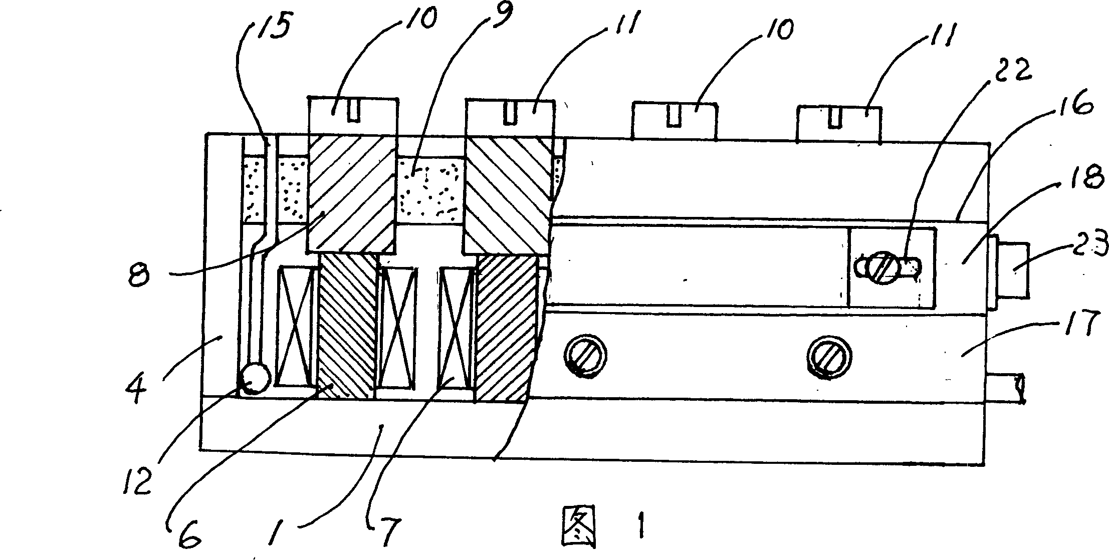
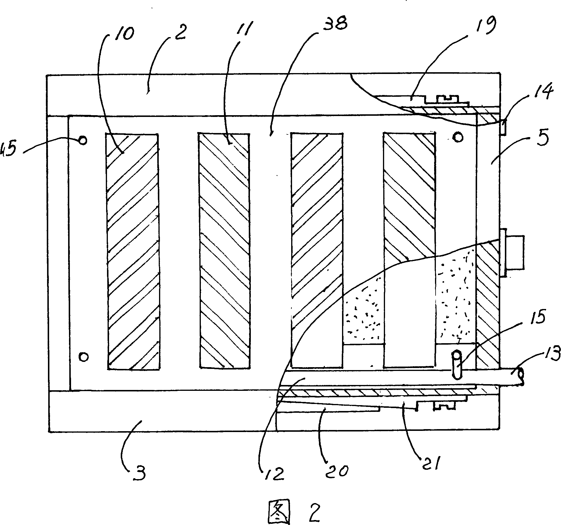
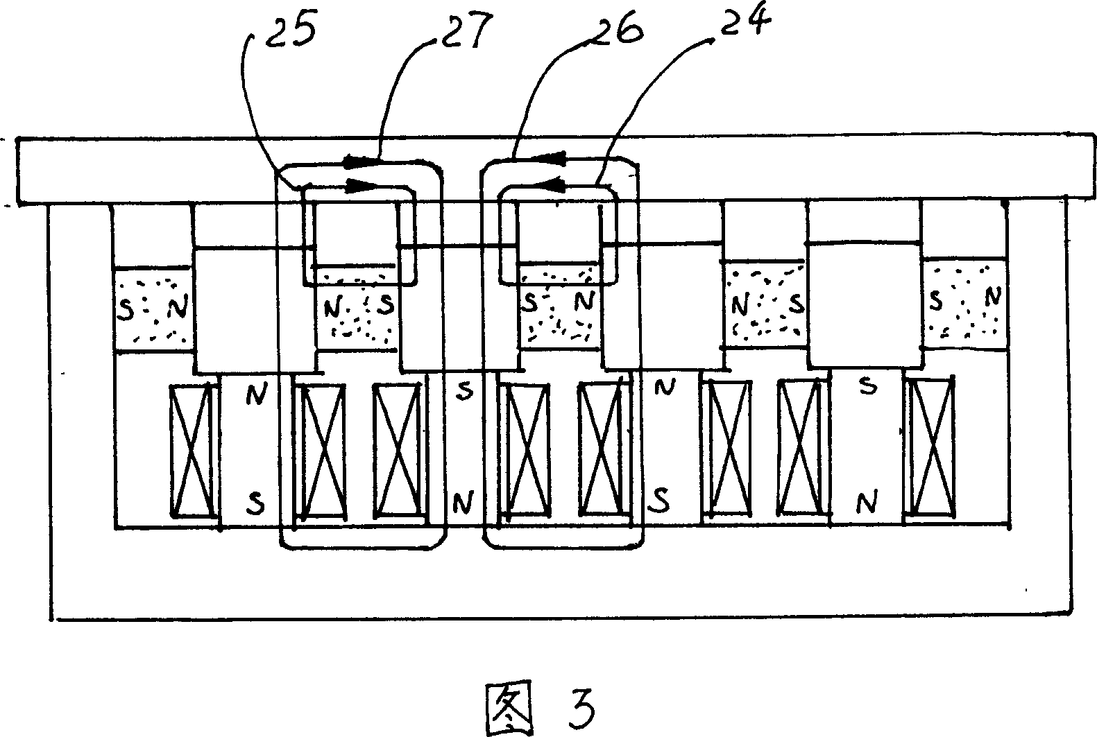
[0022] Referring to Fig. 1 and Fig. 2, the electric permanent magnet traveling fixture for transmission comprises the traveling fixture box surrounded by the base plate 1, side plates 2, 3 and end plates 4, 5 made of low carbon steel, and the base plate 1 is equipped with 2-16 groups of combined reversible magnets 6 made of AlNiCo material, each group of reversible magnets 6 is covered with an excitation coil 7, and each group of reversible magnets 6 is equipped with a bar-shaped pole piece 8, and between the bar-shaped pole pieces 8 N poles and S poles are alternately mounted with NdFeB main magnets 9, and heat-treated skimming pole caps 10 and stamping pole caps 11 are fixed alternately above the bar-shaped pole pieces 8, so that the aforementioned pole caps have a larger Excellent side shear resistance and good wear resistance. Considering that the pallet is clamped under the workpiece, when it is impacted and vibrated, dust or oxides are easy to fall on it, which will affe...


PUM


Abstract

The present invention relates to one kind of electrically permanent magnetic servo fixture for transmission and its application. The fixture includes one fixture box comprising bottom plate, side plates and end plates, several groups of reversible magnets, exciting coils around each groups of reversible magnets, pole strips set over each groups of reversible magnets, NdFeB magnets with alternately arranged N poles and S poles embedded between pole strips, grained pole crowns set alternately over the pole strips, pneumatic dust removing pipeline inside the inner cavity, and guide grooves outside the side plates for plane strip and inclined strips separately. The present invention is used as the auxiliary fixture for fast fastening and releasing punched workpiece, and has high side force resistance, no obstruction stepped shift of long steel workpiece, precise workpiece location and high punched hole position prcision.

Description

technical field [0001] The invention belongs to the field of clamping tools for mechanical processing, and in particular relates to an electric permanent magnet accompanying clamp for transmission and an application thereof that can be positioned without hindrance during continuous stamping and feeding of long steel plates by a punching machine. Background technique [0002] At present, in the mechanical processing industry, the continuous punching of long steel plates is most common in automobile beams. Due to the limited capacity of the punching machine, the length of the punch group is generally within one meter, and for processing a 12-meter-long The automobile beam workpiece needs to be punched by multiple steps, but due to the diversification of the length, width and thickness of the workpiece, the feeding method usually uses the chuck to clamp the tail end of the workpiece and push it forward, and then step and shift the punch. hole, because the chuck is clamped at th...

Claims


Application Information

Patent Timeline
Patent Type & Authority Patents(China)
IPC IPC(8): B23Q3/154B25B11/00B21D43/00B21D28/24H01F1/057
Inventor 徐式逴
Owner 刘新春
Learn More