Optical device for interactive projection display

An optical device, projection display technology, applied in the input/output of user/computer interaction, the input/output process of data processing, instruments, etc., can solve the problem of low accuracy of electronic correction, inability to achieve synchronous adjustment, complex signal processing, etc. problems, to achieve the effect of improving positioning accuracy and resolution, low distortion and high quality

Inactive Publication Date: 2007-11-07
GUANGDONG VTRON TECH CO LTD
View PDF1 Cites 0 Cited by
  • Summary
  • Abstract
  • Description
  • Claims
  • Application Information

AI Technical Summary

Problems solved by technology

Although the corresponding correction algorithm is used in the electronic aspect, on the one hand, deformation and distortion directly affect the resolution of the detection image, and the accuracy of electronic correction is not high. On the other hand, the use of electronic correction increases the cost
And because the projection lens and the photoelectric detection head are not on the same optical axis, the synchronous adjustment of the distortion cannot be realized, and the signal processing is relatively complicated.

Method used


Image

  • Optical device for interactive projection display
  • Optical device for interactive projection display
  • Optical device for interactive projection display

Examples


Embodiment 1

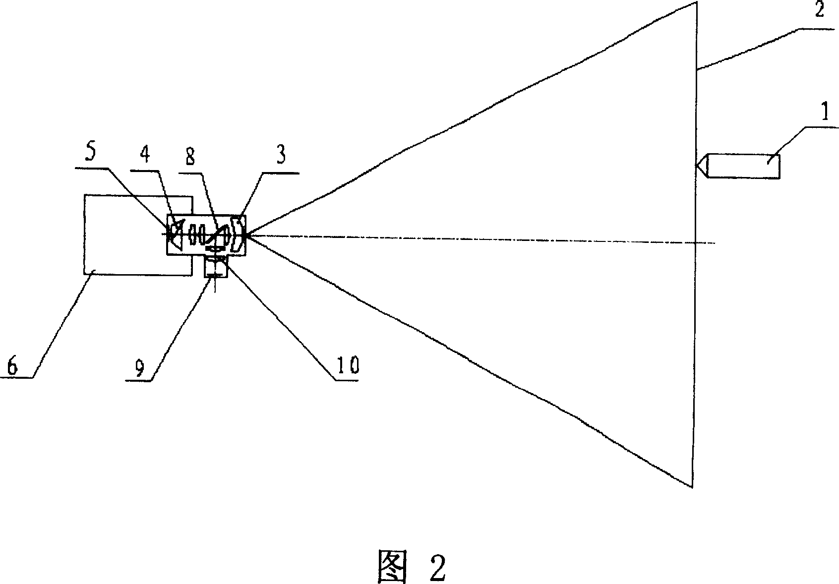
[0026] As shown in Figure 2, an optical device for an interactive projection display screen, the carrier light with position information sent by the writing pen 1 is infrared light, wherein the image generator 5, the prism 4 and the projector lens 3 are arranged in a straight line , between the optical elements of the projector lens 3, a spectroscopic mirror 8 that reflects infrared and transmits visible light is arranged. The photodetector 9 is an infrared detector, which is arranged on one side of the beam splitter 8, and its optical axis is perpendicular to the optical axis of the projector lens 3 . An additional lens 10 is arranged between the beam splitter 8 and the photodetector 9 .

Embodiment 2

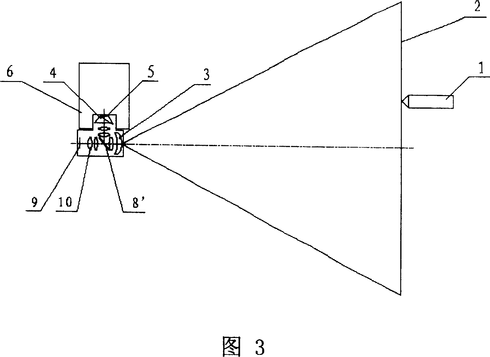
[0028] As shown in Figure 3, an optical device for an interactive projection display screen, the carrier light with position information sent by the writing pen 1 is infrared light, it adopts an L-shaped projection lens, and the optical path of the lens 3 of the projector is refracted The anti-visible and infrared-transmitting beam splitter 8' is set to replace the original mirror, which separates the projected light from the carrier light with the position information of the writing pen 1, and the photodetector 9 is arranged on the optical axis behind the beam splitter 8' to The infrared light with the position information of the writing pen is detected. An additional lens 10' is provided between the beam splitter 8' and the photodetector 9.

Embodiment 3

[0030] As shown in Figure 4, an optical device for an interactive projection display screen, the carrier light with position information sent by the writing pen 1 is infrared light, wherein the image generator 5, the prism 4 and the projector lens 3 are arranged in a straight line , the enlarged schematic view of the prism structure shown in Figure 7, the inclined surface in the prism 4 is coated with anti-infrared and transparent spectroscopic film, which separates the projected light and the carrier light with the position information of the writing pen, and the photodetector 9 is set On one side of the prism, its optical axis is perpendicular to the projection optical axis.


PUM


Abstract

The optical device for interactive projection display has beam splitting mirror in the projection optical axis to make the photoelectronic detector and the projection lens of the optical device coaxial, and photoelectronic detector possessing light energy convergence completed partially or completely with the optical elements of the projection lens. The present invention adopts beam splitting mirror for completely coaxality of the photoelectronic detector and the projection lens, eliminates the image deformation caused by off-axis of photoelectronic detector, and has raised positioning precision of the writing pen. The present invention has raised positioning precision and resolution, less image distortion, simple post-treatment and low cost.

Description

technical field [0001] The invention relates to an optical device for interactive projection display. Background technique [0002] With the rapid development of computer and other related technologies, products in the field of multimedia presentations emerge in endlessly: from projectors, video booths, to interactive electronic whiteboards, etc.; It has entered various fields such as major enterprises and institutions, teaching systems, medical institutions, and daily life, bringing users brand-new technological enjoyment. [0003] In the current photoelectric interactive projection display screen, the projection lens and the photoelectric detection head for receiving the signal of the electronic writing pen are not coaxially installed. As shown in Figure 1, that is, the structure of the existing photoelectric interactive projection display screen, the writing pen 1 is located in front of the projection display screen 2, and a projector body 6 and a photoelectric detection...

Claims


Application Information

Patent Timeline
Patent Type & Authority Patents(China)
IPC IPC(8): G06F3/033G06F3/03
Inventor 孟凡华杨学良高鑫
Owner GUANGDONG VTRON TECH CO LTD
Why Eureka
Try Eureka