A seam-type air-flow lead-jetting device

A technology of air injection and gas, which is applied in jet pumps, non-displacement pumps, machines/engines, etc. It can solve the problems of difficulty in ensuring the vacuum degree of low-pressure chambers, increased gas consumption of high-pressure gases, and complex device structures, etc., and achieves low cost. , Vacuum ejection flow rate is large, the effect of low air consumption

Inactive Publication Date: 2007-11-14
深圳市旋风流体科技有限公司
View PDF3 Cites 0 Cited by
  • Summary
  • Abstract
  • Description
  • Claims
  • Application Information

AI Technical Summary

Problems solved by technology

However, if the diameter of the circular tube is increased, the distance from the center to the edge of the circular tube will increase accordingly, making it difficult for the high-pressure gas in the center to exchange energy with the low-pressure gas at the edge, resulting in a sharp increase in the gas consumption of the high-pressure gas; if the circular tube is increased If the quantity is too large, the structure of the whole device will be complicated, the cost will increase, and the vacuum degree of the low-pressure chamber will be difficult to guarantee.

Method used


Image

  • A seam-type air-flow lead-jetting device
  • A seam-type air-flow lead-jetting device

Examples


Embodiment Construction

[0023] The present invention will be described in further detail below through specific embodiments and in conjunction with the accompanying drawings.

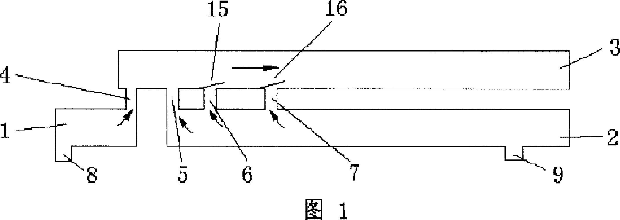
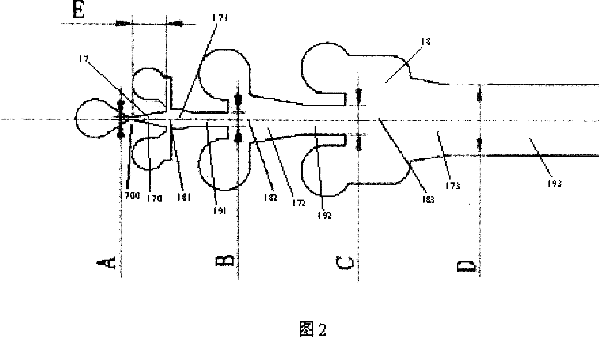
[0024] Embodiment, as shown in Fig. 1, 2, a kind of slit type airflow injection device comprises high-pressure chamber 1, jet chamber 3 and low-pressure chamber 2, and one end of jet chamber 3 communicates with high-pressure chamber 1 through channel 17, and jet chamber 3 The other end of the exhaust port 14 is set, and the high-pressure chamber 1 passes into the jet chamber 3 through the passage 17. The high-pressure gas is passed into the jet chamber 3. The side wall of the jet chamber 3 is provided with a rectangular passage port 18. The rectangular passage port 18 is divided into three-stage rectangular passage ports 181. , 182, 183, the jet chamber 3 communicates with the low-pressure chamber 2 respectively through the three-stage rectangular channel openings 181, 182, 183, and the channel 17 is composed of a rectangular s...


PUM


Abstract

This invention relates to a slot-type gas flow injection device including a high pressure cavity, an injection cavity the low pressure cavity, among which, one end of the injection device is connected with the high pressure cavity via a channel, the other end has an exhaust outlet, the high pressure cavity penetates high pressure gas to the inject cavity via the channel, a channel opening is set on the sidewall of inject cavity which is connected with a low pressure cavity via the channel, absorbs gas in the low cavity via the channel and exhausts gas via the outlet characterizing that the channel is composed of a rectangular slot and its connected wedge channel changing from narrow to wide speeds-up expansion after passing through them. The cross section of the infect cavity is rectangle.

Description

technical field [0001] The invention relates to a device for obtaining vacuum by using high-pressure gas, in particular to an airflow injection device. Background technique [0002] At present, the device that utilizes high-pressure gas to obtain vacuum adopts a circular tube for its airflow injection channel (equivalent to the jet chamber of the present invention). This device can meet the vacuum degree requirements of the low-pressure chamber when the vacuum ejection flow rate is small. However, when the required real injection flow rate is large, in order to ensure the vacuum degree of the low-pressure chamber, the diameter of the circular tube must be increased or the number of circular tubes must be increased (that is, multiple circular tubes are arranged horizontally side by side). However, if the diameter of the circular tube is increased, the distance from the center to the edge of the circular tube will increase accordingly, making it difficult for the high-pressure...

Claims


Application Information

Patent Timeline
Patent Type & Authority Patents(China)
IPC IPC(8): F04F5/20F04F5/44
Inventor 李天维
Owner 深圳市旋风流体科技有限公司
Why Eureka
Try Eureka