Flywheel generating, multifunctional system and manufacturing method and important component included in this system

A technology for a power generation system and a power generation subsystem, which is applied to electromechanical devices, electrical components, and electric components, etc., can solve the problems of low output efficiency, single function, short energy storage period and power supply period, and the magnetic pole distribution of the flywheel rotor. Safety and high output efficiency

Inactive Publication Date: 2007-11-21
吴震宇
View PDF1 Cites 0 Cited by
  • Summary
  • Abstract
  • Description
  • Claims
  • Application Information

AI Technical Summary

Problems solved by technology

[0007] The technical problem to be solved by the present invention is: mainly solve the low output efficiency of the flywheel (including magnetic levitation flywheel) power generation system in the prior art during the energy supply period, and the iron core of its armature winding hysteresis loss flywheel kinetic energy during the flywheel energy storage period, The power generation efficiency of the armature winding made of weak magnetic materials is too low, the energy storage time of the flywheel and the power generation system is short, and the flywheel continuously dissipates kinetic energy during the energy storage period. The problem of high-power output kinetic energy and electric energy, on the premise of corresponding or having the above-mentioned main problem-solving functions, solves the problem of hysteresis loss of components directly affected by the rotating excitation magnetic field of the flywheel, and solves the short energy storage period and power supply period Solve the problem that the magnetic pole distribution of the flywheel rotor is limited and single, and there is only one armature for power generation, which is greatly restricted. Solve the problem of hysteresis loss and eddy current loss of the armature core. , the problem of single function and low conversion efficiency, solve the problem that the power generation efficiency of flywheel energy storage and power generation system is not ideal, and the single function has not yet been widely used

Method used


Image

  • Flywheel generating, multifunctional system and manufacturing method and important component included in this system
  • Flywheel generating, multifunctional system and manufacturing method and important component included in this system
  • Flywheel generating, multifunctional system and manufacturing method and important component included in this system

Examples


Embodiment Construction

[0044] The present invention will be described in further detail below in conjunction with the accompanying drawings and preferred embodiments.

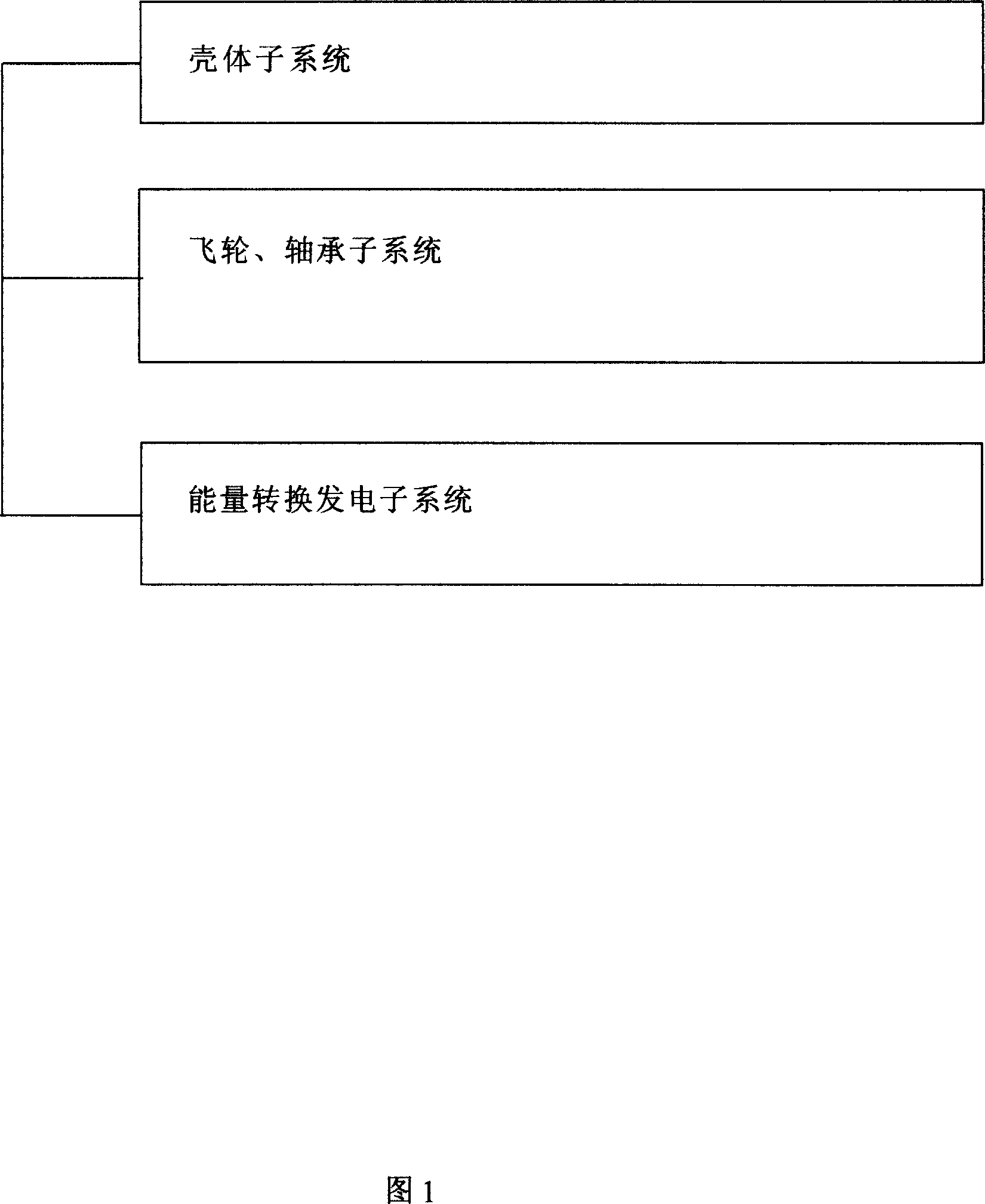
[0045] (1) Referring to accompanying drawing 1, the system structure is shown in Fig. 1, and it is composed of: housing subsystem, flywheel, bearing subsystem, energy conversion and power generation subsystem. The three subsystems included in the flywheel system are the basic components included in the flywheel power generation system described in technical solution 1 of the present invention.

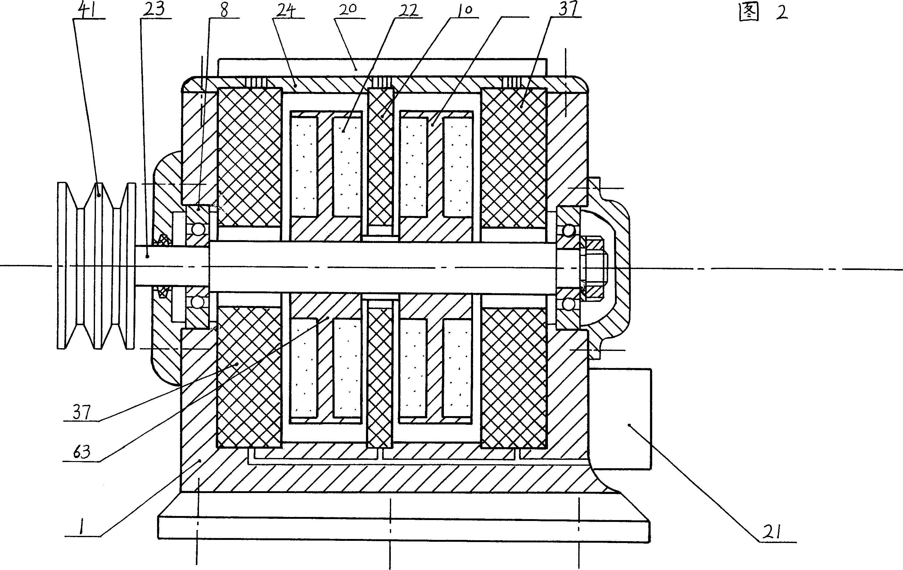
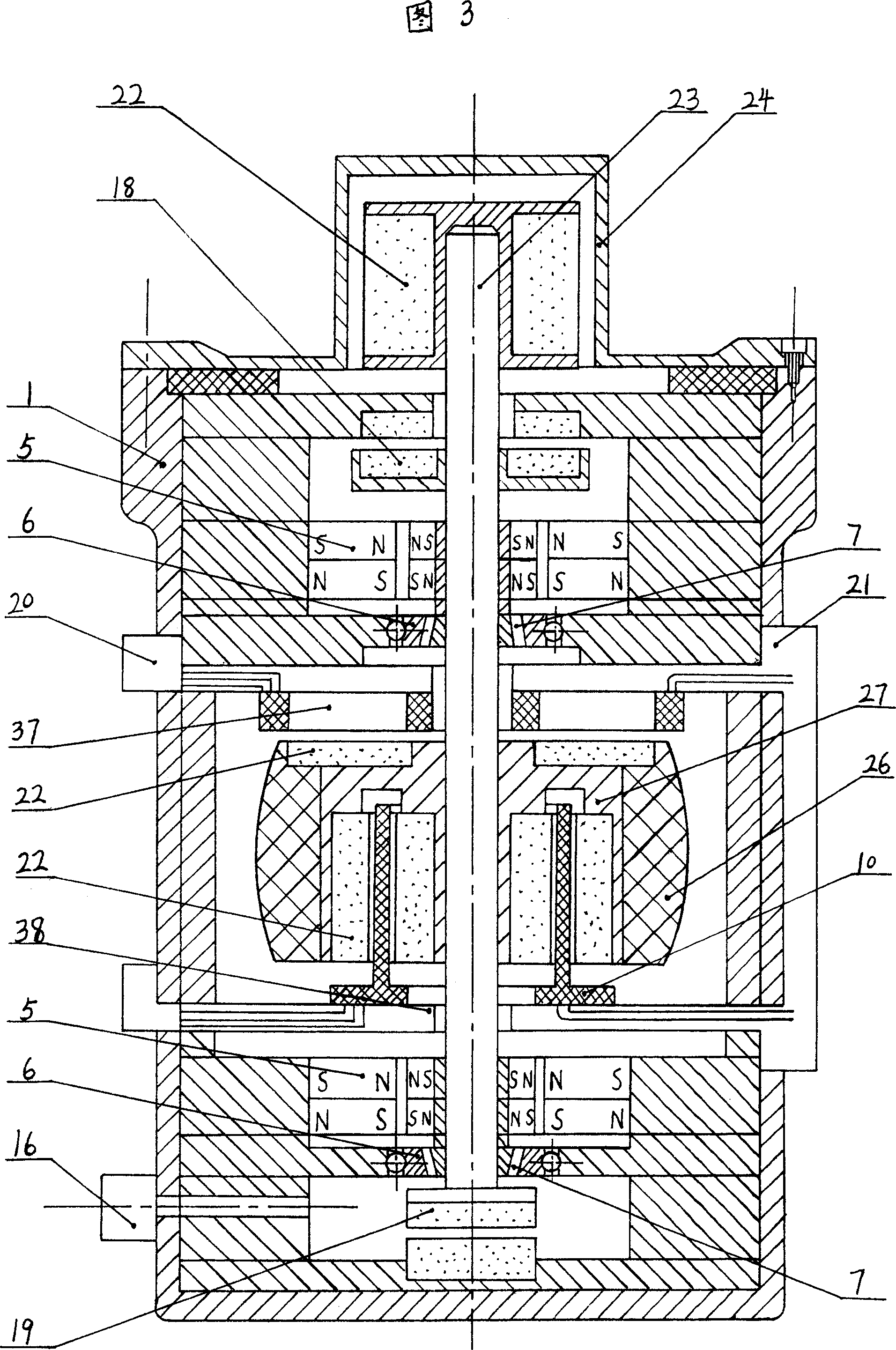
[0046] (2) The preferred embodiment of the first flywheel system, with reference to accompanying drawing 2, if divided by the three subsystems described in technical scheme 1: a housing 1, sealed electric input and output device 20, heat sink 21, sealed outer cover 24 belongs to the shell subsystem; a composite flywheel 63 (hereinafter referred to as composite flywheel) specially designed for "high magnetic permeability core winding" to expan...


PUM


Abstract

Flywheel generating multifunctional system comprising, a case subsystem, flywheel-bearing subsystem, energy conversion generating subsystem containing a multifunctional armature, power and propulsion subsystem. In the system, at least one of the following components is used, a flywheel including more than one pair of magnetic poles at the axial and radial positions respectively, a combination flywheel with enlarged magnetic pole excitation operating area, annular magnetic suspension bearing possessing constraining force of more than two two-dimensions, eccentric type ring shape magnetic suspension bearing, more than two multifunctional armatures using weak magnetic material as armature core, controllable movable armature winding with iron core made of soft magnetic material.

Description

Technical field: [0001] The invention relates to a flywheel power generation system. [0002] A flywheel power generation system is an ideal, efficient, clean, mobile or fixed system that converts mechanical energy into electrical energy with high efficiency. It can be used as a flywheel battery, and is also suitable for energy storage and power generation power systems of various motor animals. Motor vehicles in this patent document refer to machines and equipment that can operate or move; such as vehicles (motor vehicles, electric vehicles, ships, aircraft, spaceships, airplanes), mechanical equipment, electric drive equipment, electrical equipment, etc. Background technique: [0003] 1. In the prior art generator system, the core generator includes a rotor or stator made of magnetically permeable materials, armature windings, ordinary bearings, etc., and shell components made of cast iron and steel. Its transmission is mechanical transmission. All kinds of losses are h...

Claims


Application Information

Patent Timeline
Patent Type & Authority Patents(China)
IPC IPC(8): H02K5/02H02K5/04H02K7/02H02K1/27H02K7/08H02K7/09H02K1/00H02K1/12H02K3/00H02K3/02H02K3/24
CPCY02E60/16
Inventor 吴震宇
Owner 吴震宇
Why Eureka
Try Eureka