Flue gas stripping device

A stripper, flue gas technology, applied in chemical instruments and methods, petroleum industry, cracking, etc., can solve problems affecting service life, permanent distortion of heat transfer tubes, etc., to achieve reliable operation, lower operating temperature, and better results Good results

Active Publication Date: 2007-11-28
CHINA PETROLEUM & CHEM CORP +1
View PDF10 Cites 0 Cited by
  • Summary
  • Abstract
  • Description
  • Claims
  • Application Information

AI Technical Summary

Problems solved by technology

The disadvantage is that the heat transfer tube between the upper header and the lower header is prone to permanent distortion at high temperature and affects its service life
[0011] Although there are many patented technologies on flue gas stripping and catalyst cooling, there is no report on the catalytic cracking regenerant flue gas stripper with catalyst cooling function

Method used


Image

  • Flue gas stripping device
  • Flue gas stripping device
  • Flue gas stripping device

Examples


Embodiment

[0036] This embodiment illustrates: the beneficial effect brought by adopting the flue gas stripper of the present invention on the FCC device.

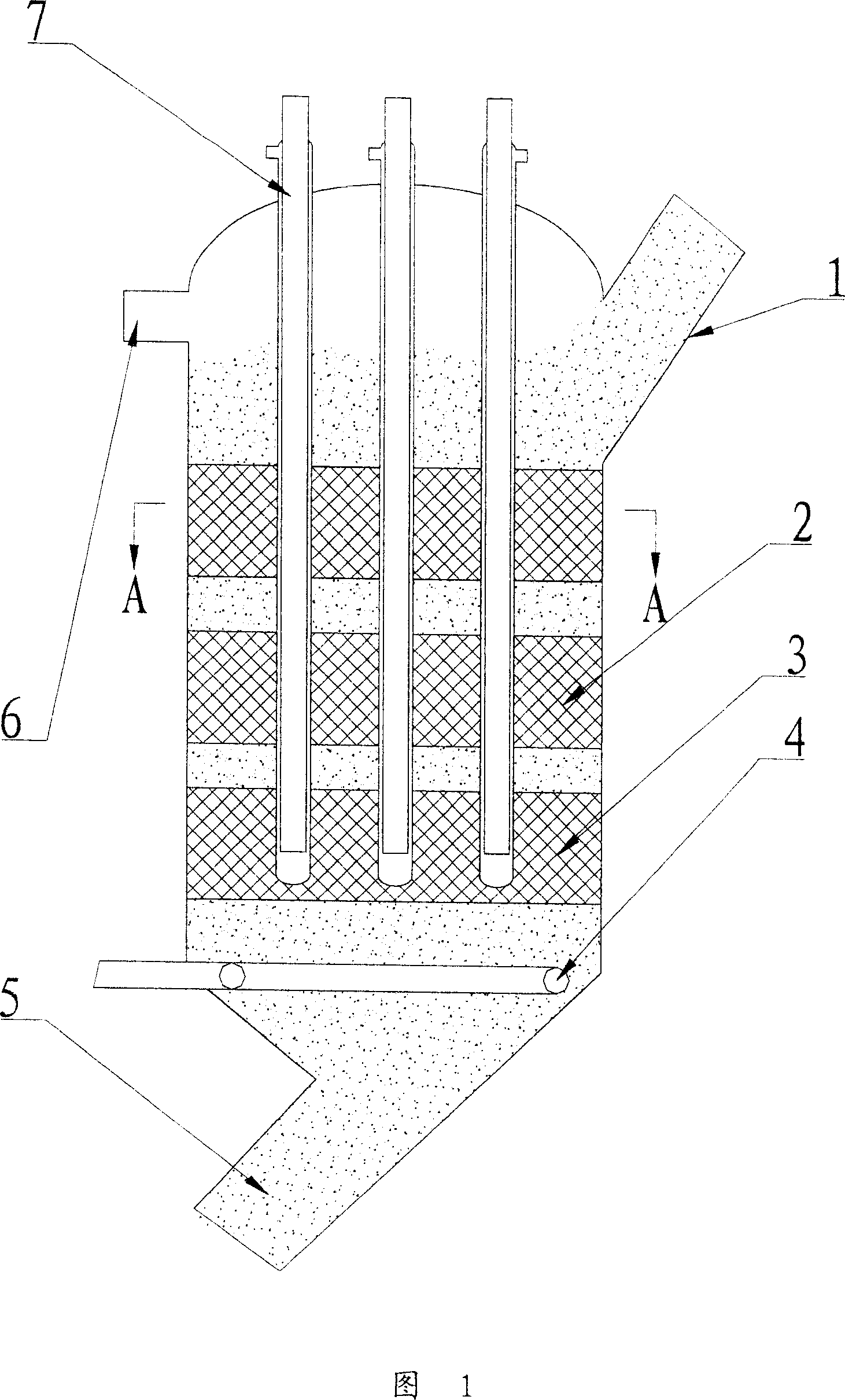
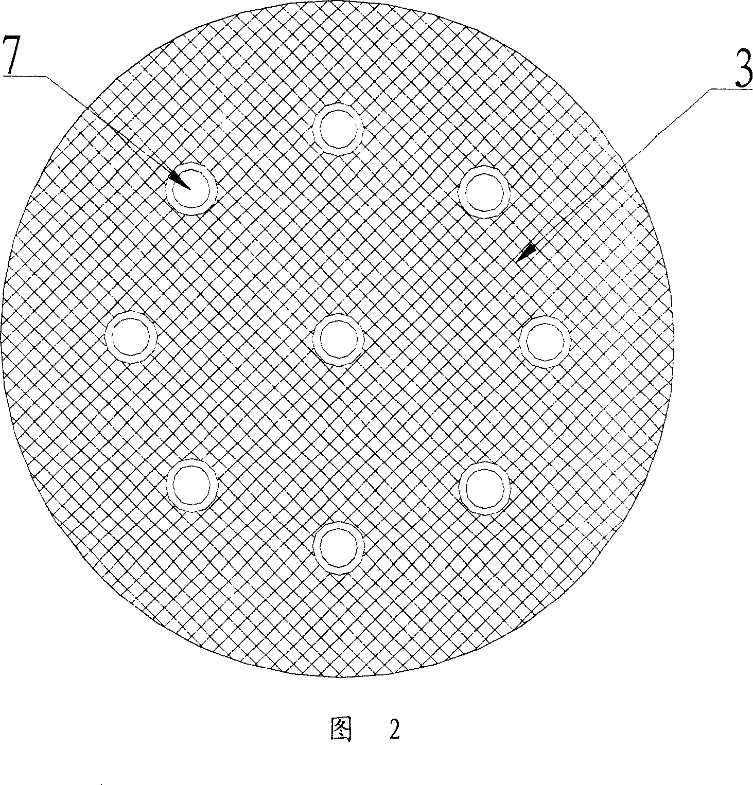
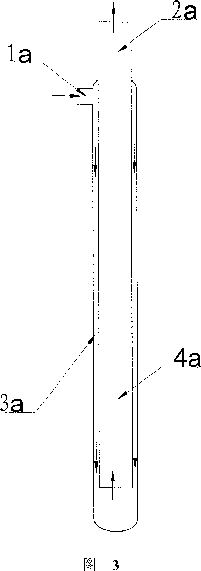
[0037] at a processing capacity of 100 x 10 4 Ton / year heavy oil catalytic cracking unit is transformed, and the flue gas stripper of the present invention is added. The flue gas stripper has a diameter of 2400mm and a height of 5650mm. It has three layers of internal components described in USP6224833, and the filler has a porosity of 75%. The stripper is equipped with a total of 20 nail heads to take heat pipes, the length of the heat pipes is 5.1m, and the heat transfer area of ​​a single pipe is 5.6m 2 , with a total heat transfer area of ​​112m 2 , The heat load is 1.56×10⁷W. Steam is used as the stripping medium, and the linear velocity of the stripping steam is 0.2m / s. After the industrial application test, the temperature of the dense-phase bed of the regenerator dropped from 705° to 698°, and the content of non-hydrocarb...


PUM

PropertyMeasurementUnit
heightaaaaaaaaaa
porosityaaaaaaaaaa

Abstract

This invention relates to smoke stripper, which comprises the following parts: regeneration catalyze agent conductive tube, smoke stripper cylinder, stripper filling materials, stripper medium distributor, regeneration inclined tube, stripper medium output tube, heat fetching tube, wherein, the conductive tube and the stripper medium output tube are located on the stripper and the inclined tube is located on the bottom of the stripper with more than one layers of materials on the stripper; the striper medium distributor is located below the filling materials; the heat fetching tube medium conductive end and output end are located outside the smoke stripper with rest inside. The stripper has regeneration agent to remove smoke and lower double functions.

Description

technical field [0001] The invention belongs to petroleum hydrocarbon catalytic conversion equipment, more specifically, a stripper for removing flue gas entrained by a regenerated catalyst. Background technique [0002] In the catalytic cracking unit, as the catalyst circulates, part of the flue gas will be carried by the regenerated catalyst to the riser reactor. According to literature reports, this part of flue gas accounts for about 1-3% of the catalyst circulation. After passing through the riser and settler, this part of the flue gas enters the rich gas compressor with the dry gas, which increases the load of the rich gas compressor and affects the processing capacity and energy consumption of the device. Therefore, it should be reacted when the regenerated catalyst enters the riser This part of the flue gas is removed before the device. [0003] In the catalytic cracking unit (FCC) of the refinery, especially in the catalytic cracking of heavy oil (RFCC), in recent...

Claims


Application Information

Patent Timeline
Patent Type & Authority Patents(China)
IPC IPC(8): B01J38/06B01J8/18C10G11/18
Inventor 张永民侯栓弟李松年许克家张占柱张久顺龙军赵俊鹏
Owner CHINA PETROLEUM & CHEM CORP
Why Eureka
Try Eureka