Regenerated catalyst steam-stripping device of flue gas

A technology for regenerating catalysts and strippers, which is used in catalyst regeneration/reactivation, physical/chemical process catalysts, chemical instruments and methods, etc. The effect of operating temperature, improving stripping efficiency, and flexible heat extraction

Active Publication Date: 2007-09-19
CHINA PETROLEUM & CHEM CORP
View PDF6 Cites 0 Cited by
  • Summary
  • Abstract
  • Description
  • Claims
  • Application Information

AI Technical Summary

Problems solved by technology

The disadvantage is that the heat transfer tube between the upper header and the lower header is prone to permanent distortion at high temperature and affects its service life
[0011] Although there are many patented technologies on flue gas stripping and catalyst cooling, there is no report on the catalytic cracking regenerant flue gas stripper with catalyst cooling function

Method used


Image

  • Regenerated catalyst steam-stripping device of flue gas
  • Regenerated catalyst steam-stripping device of flue gas
  • Regenerated catalyst steam-stripping device of flue gas

Examples


Embodiment

[0040] This embodiment illustrates: the beneficial effect brought by adopting the flue gas stripper of the present invention on the FCC device.

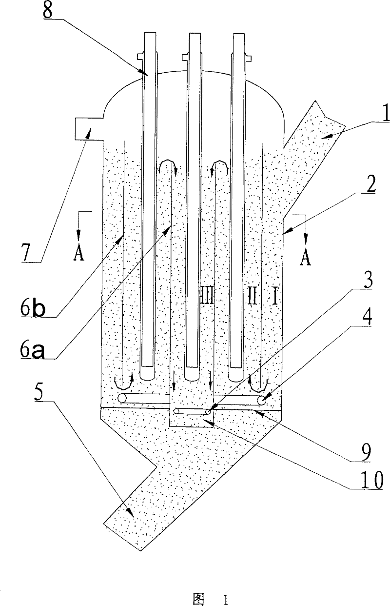
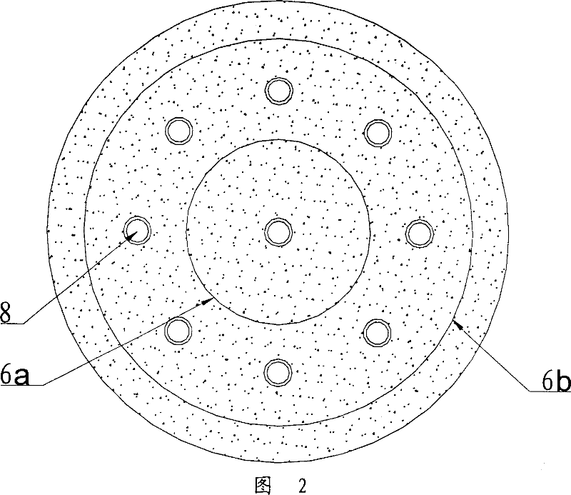
[0041] at a processing capacity of 100 x 10 4 Ton / year heavy oil catalytic cracking unit is transformed, and the flue gas stripper of the present invention is added. The flue gas stripper has a diameter of 2400mm and a height of 5650mm. The structure of this stripper is shown in Figure 1, wherein, the ratio of the effective cross-sectional area of ​​I, II and III three districts is 1.5: 2: 1, the lower end of inner sleeve 6b is to the upper end surface of stripping medium distributor 4 The vertical distance of 10 centimeters, inner sleeve 6b and inner sleeve 6a, the height difference of the two upper ends is 20 centimetres. The stripper is equipped with a total of 20 nail heads to take heat pipes, the length of the heat pipes is 5.1m, and the heat transfer area of ​​a single pipe is 5.6m 2 , with a total heat transfer area of ​​11...


PUM


Abstract

he regenerated catalyst gas stripper comprises: arranging regenerated catalyst lead-in tube (1) and stripping medium lead-off tube (7) on top of the stripper and regenerated inclined tube (5) on bottom of the stripper; fixing and connecting the bottom separation plate (9) with medium distributor (4) on top and stripper cylinder and catalyst outlet pipe (10); arranging the inner sleeve (6b) on top of distributor (4) with the top end of inner sleeve (6a) in inner sleeve (6b) lower than inner sleeve (6b) and the bottom end passing distributor (4) and separation plate (9) to form outlet pipe (10); arranging stripping medium distributor (3) in catalyst outlet pipe (10 under the heat tube (8) with lead-in and lead-out ends for heat medium outside the stripper and other part in stripper. This product has dual-function both for stripping and cooling.

Description

technical field [0001] The invention belongs to petroleum hydrocarbon catalytic conversion equipment, more specifically, a stripper for removing flue gas entrained by a regenerated catalyst. Background technique [0002] In the catalytic cracking unit, as the catalyst circulates, part of the flue gas will be carried by the regenerated catalyst to the riser reactor. According to literature reports, this part of flue gas accounts for about 1-3% of the catalyst circulation. After passing through the riser and settler, this part of the flue gas enters the rich gas compressor with the dry gas, which increases the load of the rich gas compressor and affects the processing capacity and energy consumption of the device. Therefore, it should be reacted when the regenerated catalyst enters the riser This part of the flue gas is removed before the device. [0003] In the catalytic cracking unit (FCC) of the refinery, especially in the catalytic cracking of heavy oil (RFCC), in recent...

Claims


Application Information

Patent Timeline
Patent Type & Authority Patents(China)
IPC IPC(8): B01J8/00B01J38/00
Inventor 张永民侯栓弟李松年许克家张占柱张久顺龙军赵俊鹏
Owner CHINA PETROLEUM & CHEM CORP
Why Eureka
Try Eureka