Supercharge Your Innovation With Domain-Expert AI Agents!

Buttonhole machine

A sewing machine and buttonhole technology, applied to sewing machine components, sewing equipment, cloth pressing mechanism, etc., can solve problems such as warping, achieve light structure weight, reduce material consumption, and work quickly and accurately.

Inactive Publication Date: 2007-11-28
DURKOPP ADLER GMBH
View PDF6 Cites 0 Cited by
  • Summary
  • Abstract
  • Description
  • Claims
  • Application Information

AI Technical Summary

Problems solved by technology

[0004] A disadvantage of the known sewing machines is that the sewing material clips have to be made fairly firm; if they are not, they will warp due to the resulting clamping forces

Method used


Image

  • Buttonhole machine
  • Buttonhole machine
  • Buttonhole machine

Examples


Embodiment Construction

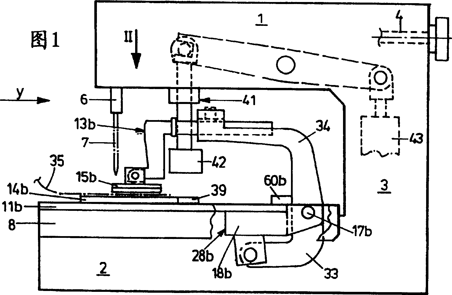
[0024] As shown in FIG. 1 , the buttonhole sewing machine is C-shaped, having a top arm 1 , a bottom base plate 2 in the form of a housing, and an approximately vertical bracket 3 connecting the top arm 1 and the bottom base plate 2 . The arm shaft 4 is generally supported in the arm 1; it can be driven by a motor 5, which is only schematically indicated in FIG. 8 . The actuation of the vertically movable needle bar 6 and the needle 7 as well as their jogging drive originate from the arm shaft 4 .

[0025] An x-y slide table 8 is arranged on the base plate 2, and the x-y slide table 8 is a cross slide, which can move in two horizontal coordinate directions, ie, in x and y directions. An x-y slide 8 of conventional design is known, for example, from DE 19807771 A1 (corresponding to US patent 6095066). The drive of the x-y slide 8 takes place via drives only roughly outlined in FIG. 8 , namely an x ​​drive 9 and a y drive 10 , which are electric position-controlled motors, pref...


PUM


Abstract

A buttonhole sewing machine comprises work piece clamps with displacement drives for displacement from an initial position of spread by a length of spread into a final position of spread. The work piece clamp comprises a supporting plate for accommodation of a work piece and a clamping plate mounted on the supporting plate. A clamping drive for actuation of the clamping plate supports itself on the supporting plate.

Description

technical field [0001] The invention relates to a buttonhole sewing machine comprising a needle drivable by an arm shaft; an x-y slide movable in the x direction by an x ​​drive and in the y direction by a y drive , and the x-y slide table supports first and second sewing material clamps, the first and second sewing material clamps are mounted to be movable relative to each other, and the x-y slide table includes a movement drive for making the sewing material clamps from the initial The deployed positions are moved relative to each other by a spread length to a final deployed position. Background technique [0002] JUKI MEB-3200 Instruction Manual Leaflet no. 02 29343316 discloses a common type of (lock) buttonhole sewing machine. It consists of an x-y slide that can be moved on the sewing plane by two stepper motors as x and y drives. Two sewing material clamps are arranged on the x-y slide for clamping the sewing material thereon. Via a pneumatic cylinder, they are mov...

Claims


Application Information

Patent Timeline
Patent Type & Authority Patents(China)
IPC IPC(8): D05B3/06D05B29/00D05B29/02D05B3/08
CPCD05B29/00D05B3/08D05B3/06
Inventor H·弗兰辛A·奥泊恩德费尔T·亚诺哈
Owner DURKOPP ADLER GMBH
Features
  • R&D
  • Intellectual Property
  • Life Sciences
  • Materials
  • Tech Scout
  • Unparalleled Data Quality
  • Higher Quality Content
  • 60% Fewer Hallucinations
Learn More