Novel thermal insulation system for free jet flow force measuring test model

A force measurement test and model technology, which is applied in the field of new thermal insulation systems for free jet force measurement test models, can solve the problems of no thermal insulation and cooling system, distortion of force measurement data, test failure, etc., and achieves remarkable thermal insulation and cooling effect. The effect of low structural weight and low structural weight

Active Publication Date: 2016-12-07
CHINA ACAD OF AEROSPACE AERODYNAMICS
View PDF7 Cites 12 Cited by
  • Summary
  • Abstract
  • Description
  • Claims
  • Application Information

AI Technical Summary

Problems solved by technology

Because the model and the force measuring system are in the high-temperature airflow for a long time, the temperature of the model and the balance will inevitably increase continuously. Excessively high temperature will cause a large temperature drift of the balance strain gauge, resulting in serious distortion of the force measurement data and even damage the balance. Strain gauges caused the test to fail
Since work on dynamometric tests in free jets has not been carried out very long, no standardized thermal insulation cooling system is available

Method used


Image

  • Novel thermal insulation system for free jet flow force measuring test model
  • Novel thermal insulation system for free jet flow force measuring test model
  • Novel thermal insulation system for free jet flow force measuring test model

Examples


Embodiment Construction

[0032] The present invention will be further described in detail below in conjunction with the accompanying drawings, so that those skilled in the art can implement it with reference to the description.

[0033] It should be understood that terms such as "having", "comprising" and "including" used herein do not exclude the presence or addition of one or more other elements or combinations thereof.

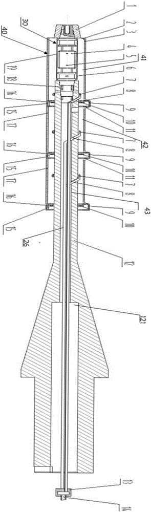
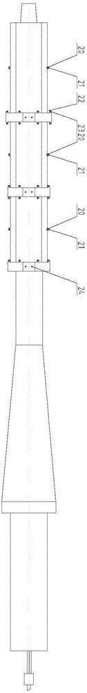
[0034] like figure 1 , 2 As shown, the free jet dynamometric test model novel heat insulation system of the present invention comprises:

[0035] Force measuring balance 4, it is arranged on model cavity (not shown in the figure), and one end of described force measuring balance 4 is connected to model cavity; For example, the front end of described force measuring balance 4 is connected to model cavity;

[0036] A strut 12, one end of which is connected to the other end of the force measuring balance 4, such as the tail end;

[0037] Balance protective cover 30, its cover is lo...


PUM


Abstract

The invention discloses a novel thermal insulation system for a free jet flow force measuring test model. The novel thermal insulation system includes a force measuring balance, a supporting rod, a balance protection cover, a thermal insulation assembly and a gas cooling assembly; the force measuring balance is arranged in a mould inner cavity; one end of the force measuring balance is connected with the mould inner cavity; one end of the supporting rod is connected with the other end of the force measuring balance; the balance protection cover is arranged on the force measuring balance in a covering manner so as to realize thermal insulation protection for the force measuring balance; the thermal insulation assembly includes a thermal insulation sleeve which is arranged along the circumferential direction of the supporting rod; a sealing space is defined between the thermal insulation sleeve and the outer circumferential surface of the supporting rod; labyrinth seal components are arranged on the supporting rod at intervals so as to divide the sealing space into at least three intervals; and the gas cooling assembly includes gas jetting rings which are located in the intervals and sleeve the outer circumference of the supporting rod, and a cold gas pipeline which is communicated with the gas jetting rings, wherein the cold gas pipeline is connected with a high-pressure cold gas source, and the gas jetting rings jet out a cooling gas to decrease the temperature of the mould inner cavity. According to the novel thermal insulation system of the invention, a plurality of thermal insulation and cooling means are adopted, and therefore, the novel thermal insulation system is remarkable in cooling effect and compact in structure, and can effectively control the temperature of the balance.

Description

technical field [0001] The invention relates to wind tunnel test equipment, and more specifically, the invention relates to a new type of heat insulation system for a free-jet dynamometric test model. Background technique [0002] With the continuous development of my country's aerospace technology and the needs of national strategies, hypersonic vehicles have gradually become the focus of national aerospace development. Different from conventional low-speed aircraft, hypersonic flight has time scale, Reynolds number, temperature, and thermochemical effects. Wind tunnel tests need to simulate airflow speeds above Mach 5, high temperatures around 2000K, and characteristic times that satisfy temperature effects. scale. The free-jet wind tunnel can provide high-speed reverse heated airflow to simulate the typical hypersonic flight environment, and solve the influence of the comprehensive mechanical environment during the flight process on the aerodynamic characteristics of the...

Claims


Application Information

Patent Timeline
Patent Type & Authority Applications(China)
IPC IPC(8): G01M9/04
CPCG01M9/04
Inventor 钱丹丹杨辉李广良
Owner CHINA ACAD OF AEROSPACE AERODYNAMICS
Why Eureka
Try Eureka