Heating apparatus

A heat supply device and heat source technology, applied in heat storage heaters, fluid heaters, heating element materials, etc., can solve problems such as difficult to achieve comfortable and environmentally friendly heating, reduce resistance and power consumption, and increase indoor temperature , The effect of reducing heating costs

Inactive Publication Date: 2008-01-02
金英淑
View PDF6 Cites 0 Cited by
  • Summary
  • Abstract
  • Description
  • Claims
  • Application Information

AI Technical Summary

Problems solved by technology

Because this kind of fan heater system has a built-in burner, it produces combustion noise, vibration noise and odorous gas during operation, making it difficult to achieve comfortable and environmentally friendly heating

Method used


Image

  • Heating apparatus
  • Heating apparatus
  • Heating apparatus

Examples


Embodiment Construction

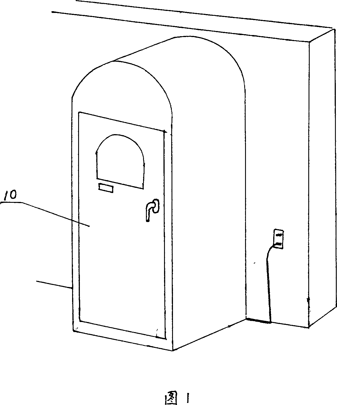
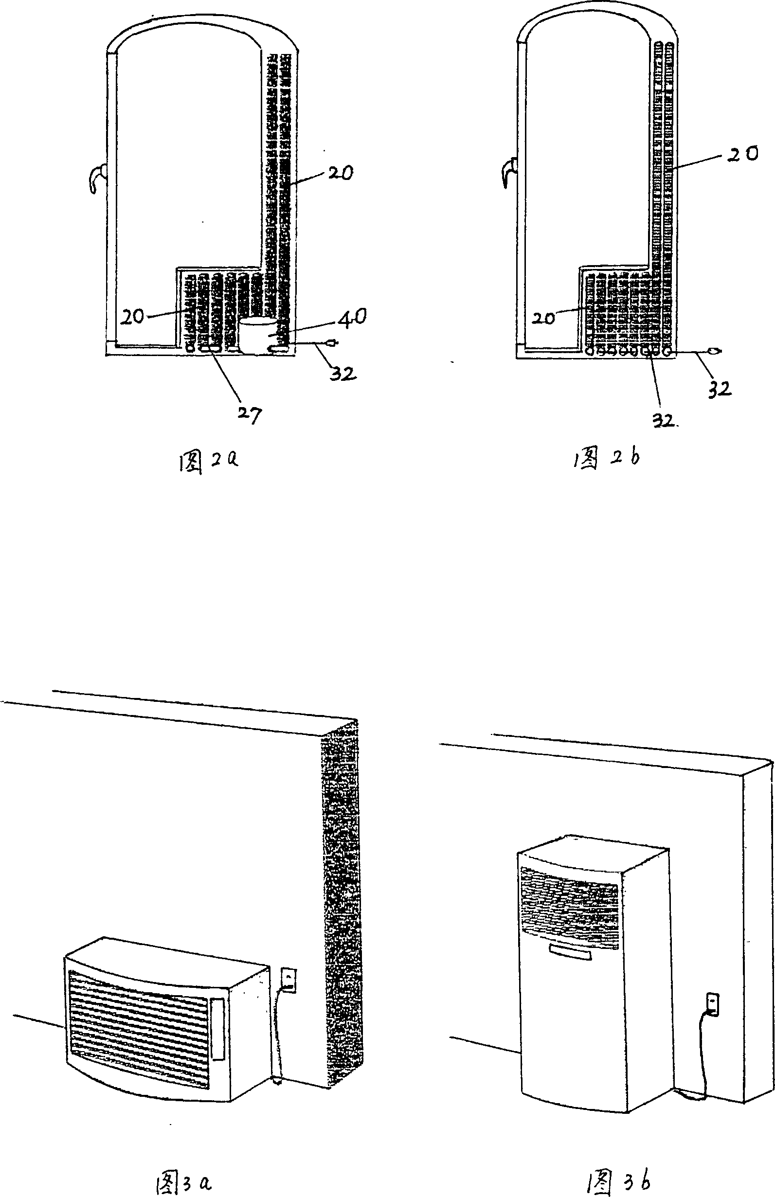
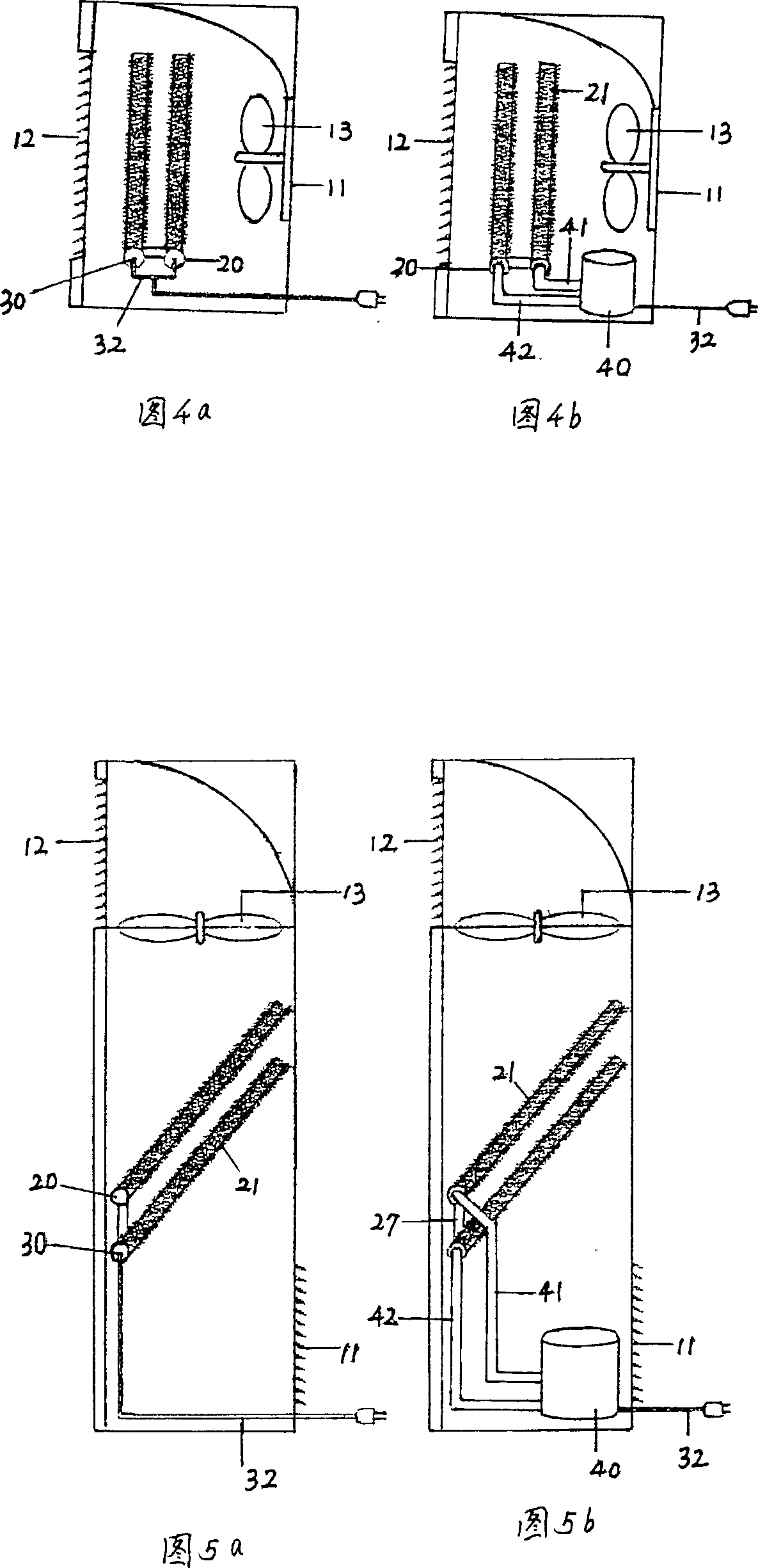
[0034] The present invention adopts a vacuum thermosiphon method with high heating effect and a carbon activated carbon fiber heating method with low power consumption and high heat acquisition in a short time. The heating method is selectively used by electric or boiler warm water to generate heat required for heating. Method to make home sauna, radiator and warm air blower. As shown in Figures 1-10, the present invention includes a heat pipe outer tube 23 and a heat pipe inner tube 24. A heat transfer medium 25 is inserted between the heat pipe outer tube 23 and the heat pipe inner tube 24 to form a thermosiphon type heat pipe 20. The heat pipe is connected by the heat pipe connection tube 27. The heat pipe outer pipe 23 is connected with a heat conduction heat release pipe 21. The heat conduction heat release pipe 21 is equipped with radiating fins 22, and the carbon activated carbon fiber 31 is inserted into the heat pipe inner pipe 24. The carbon activated carbon fiber heatin...


PUM


Abstract

This invention relates to a heat-supply device, which includes the heat conduct external pipe, the heat conduct inner pipe, the heat conduct that inserts the heat medium between the heat conduct external pipe and the heat conduct inner pipe to form the heat siphon tube, wherein the matrix active carbon fiber heating tube that uses the matrix active carbon as the heat source is inserted into the heat conduct inner pipe, the heat conduct inner pipe connects with the small-sized boiler. This invention decreases the resistance and the electricity consuming quantity to a maximum limit, and by using low voltage and least warm water, it produces a large quantity of high heat.

Description

Technical field [0001] The invention relates to a heating device, in particular to a heating device using heat pipes, heating tubes and carbon activated carbon fibers as heating elements, suitable for electric and warm-water household saunas, radiators and warm air blowers, etc., and can also be applied For geothermal heating. Background technique [0002] The home sauna system that is commonly used now consumes a lot of power, and the electricity bill is expensive, and the interrupter is often activated when it is used at the same time with other electrical appliances, which often cuts off the office or home electricity. [0003] The commonly used equipment and facilities of the radiator and fan heating system now have hot water supply connecting hoses and ducts buried in the indoor floor or wall, so the thermal conductivity is very low. Therefore, compared with the heat of the boiler, the heating effect of increasing the indoor temperature is significantly reduced, and these ho...

Claims


Application Information

Patent Timeline
Patent Type & Authority Patents(China)
IPC IPC(8): F24H7/02F24H9/18H05B3/14
Inventor 金英淑
Owner 金英淑
Why Eureka
Try Eureka