Jack catch for clamping workpiece or cutting tool

A cutting tool and workpiece technology, applied in the field of clamping devices, can solve the problems of difficult processing and large cutting volume of helical teeth, and achieve the effect of simple structure, small processing area and high dimensional accuracy

Inactive Publication Date: 2008-01-30
ZHEJIANG UNIV
View PDF5 Cites 2 Cited by
  • Summary
  • Abstract
  • Description
  • Claims
  • Application Information

AI Technical Summary

Problems solved by technology

However, since the helical teeth spread over the entire connecting surface of the base claw, the cutting amount of the helical teeth is large and there is a strong impact during processing; at the same time, it is very difficult to process the intersecting helical teeth to obtain high dimensional accuracy

Method used


Image

  • Jack catch for clamping workpiece or cutting tool
  • Jack catch for clamping workpiece or cutting tool
  • Jack catch for clamping workpiece or cutting tool

Examples


Embodiment Construction

[0018] The present invention will be further illustrated by the accompanying drawings and examples.

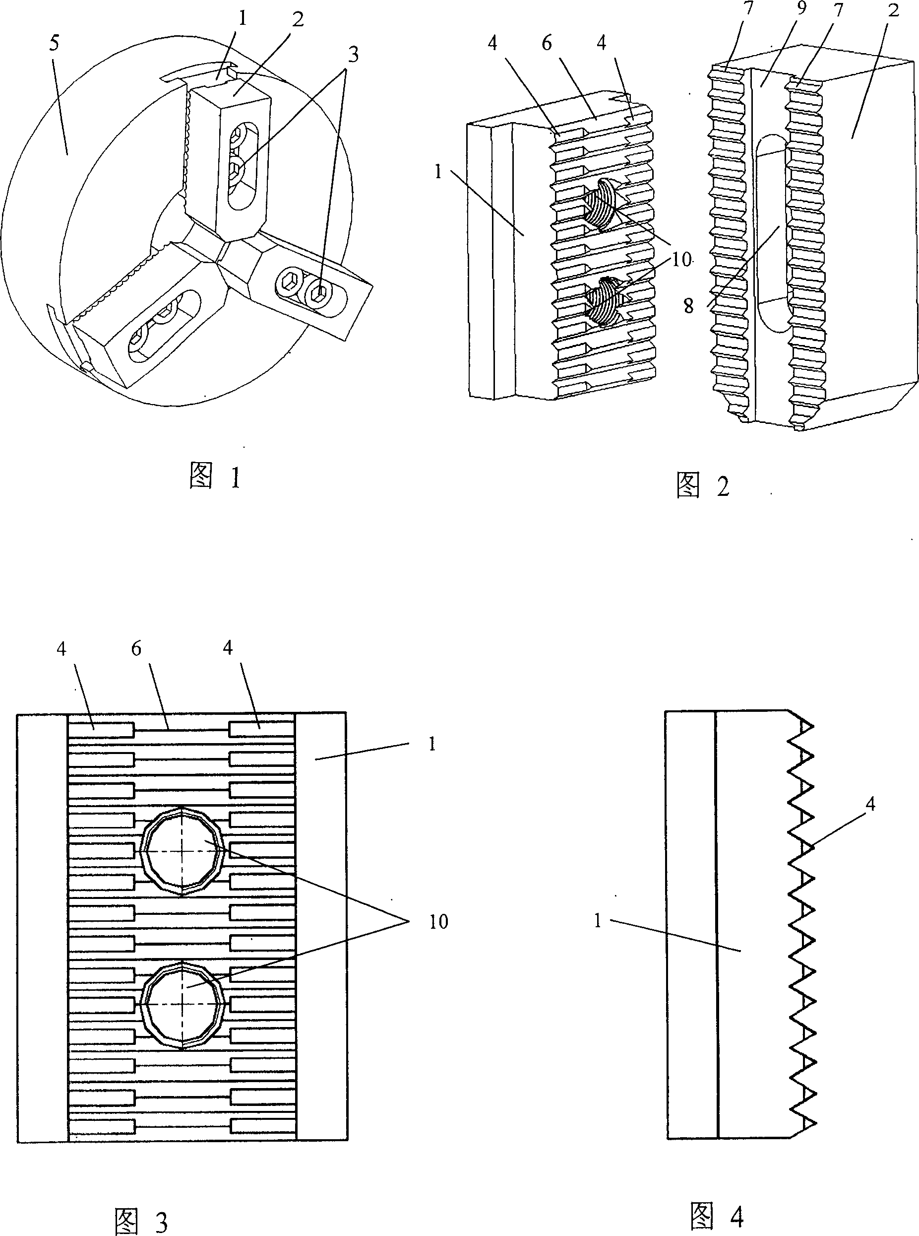
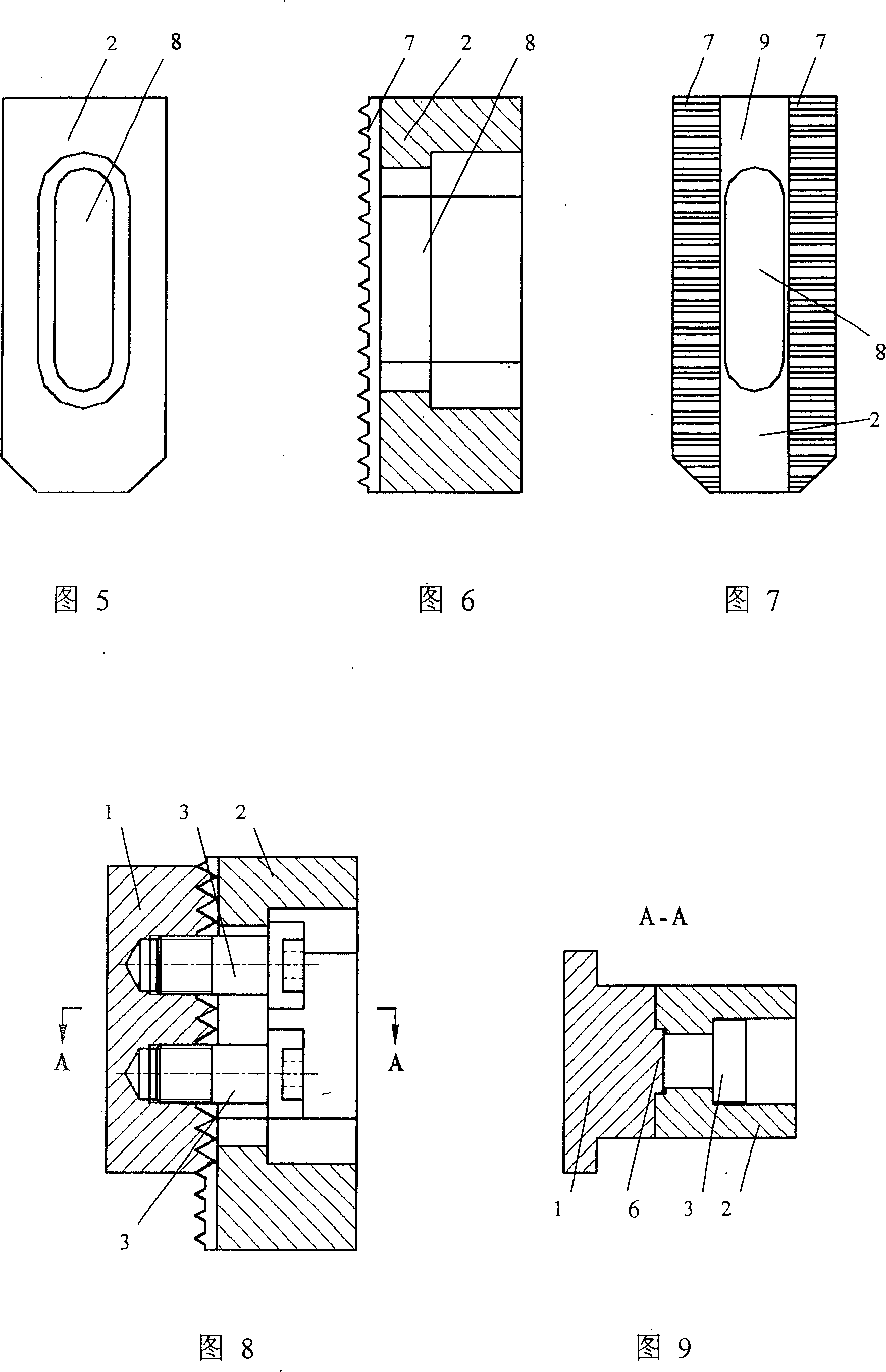
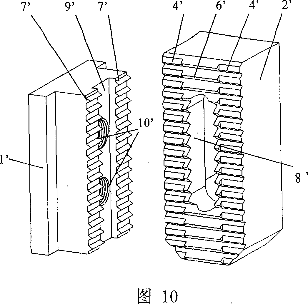
[0019] As shown in Figures 1 to 9, the present invention includes a toothed base claw 1 matched with a toothed high claw 2, and connected with a screw 3 as a whole. One side of the base claw 1 is provided with base claw triangular teeth 6 arranged equidistantly, and the tooth tops on both sides of the base claw triangular teeth 6 are flattened into base claw trapezoidal teeth 4, and the base claw triangular teeth 6 in the middle of the base claw 1 are provided with base claw screws Hole 10, one side of the high claw 2 is provided with the same pitch as the base claw 1, and the tooth top is triangular, and the tooth groove is trapezoidal high claw teeth 7, and the middle of the toothed side of the high claw 2 is provided with a horizontal positioning groove for the high claw 9. There is a high claw waist-shaped hole 8 parallel to the high claw lateral positioning groove 9 in th...


PUM


Abstract

A clamping jaw for claming workpiece or cutting tool is composed of a basic jaw with triangular teeth whose tooth top has both truncated sides to become trapezoidal side teeth and the screw hole at the position of triangular teeth, and a high jaw with triangular teeth and trapezoidal tooth spaces for matching with the trapezoidal side teeth of basic jaw, transverse locating slot on the tooth and waist hole.

Description

technical field [0001] The invention relates to a clamping device for a workpiece or a tool of a machine tool, in particular to a jaw for clamping a workpiece or a tool. Background technique [0002] The jaw stroke of the power chuck of the CNC machine tool is small. In order to expand its clamping diameter range, the separation jaw is often used, that is, the base jaw and the high jaw. Locate and connect the base height claw, and adjust the radial position of the T-slot bolt to adjust the radial position of the height claw. However, since the bolt head of the T-slot bolt is located in the radial groove of the base jaw, in a full-seal chuck, the radial position of the high jaw cannot be adjusted in a large range, which limits the clamping diameter range. [0003] DE10045257 proposes to use intersecting helical teeth to simultaneously realize the radial positioning and lateral positioning of the base claw and the high claw, and the bolt head of the connecting bolt is located...

Claims


Application Information

Patent Timeline
Patent Type & Authority Patents(China)
IPC IPC(8): B23B31/02B23B31/103
Inventor 杨华勇周城龚国芳
Owner ZHEJIANG UNIV
Why Eureka
Try Eureka