Liquid-detecting device and liquid container with the same

A technology for detection devices and liquid containers, applied in liquid level indicators for physical variable measurement, printing, etc., can solve problems such as cracks in the piezoelectric film 160

Inactive Publication Date: 2008-02-27
SEIKO EPSON CORP
View PDF7 Cites 0 Cited by
  • Summary
  • Abstract
  • Description
  • Claims
  • Application Information

AI Technical Summary

Problems solved by technology

Therefore, cracks are generated on the piezoelectric film 160 at positions corresponding to the edges of the cavity 162.

Method used


Image

  • Liquid-detecting device and liquid container with the same
  • Liquid-detecting device and liquid container with the same
  • Liquid-detecting device and liquid container with the same

Examples


Embodiment Construction

[0088] Next, a liquid detection device and an ink cartridge (liquid container) equipped with the liquid detection device according to an embodiment of the present invention will be described with reference to the drawings.

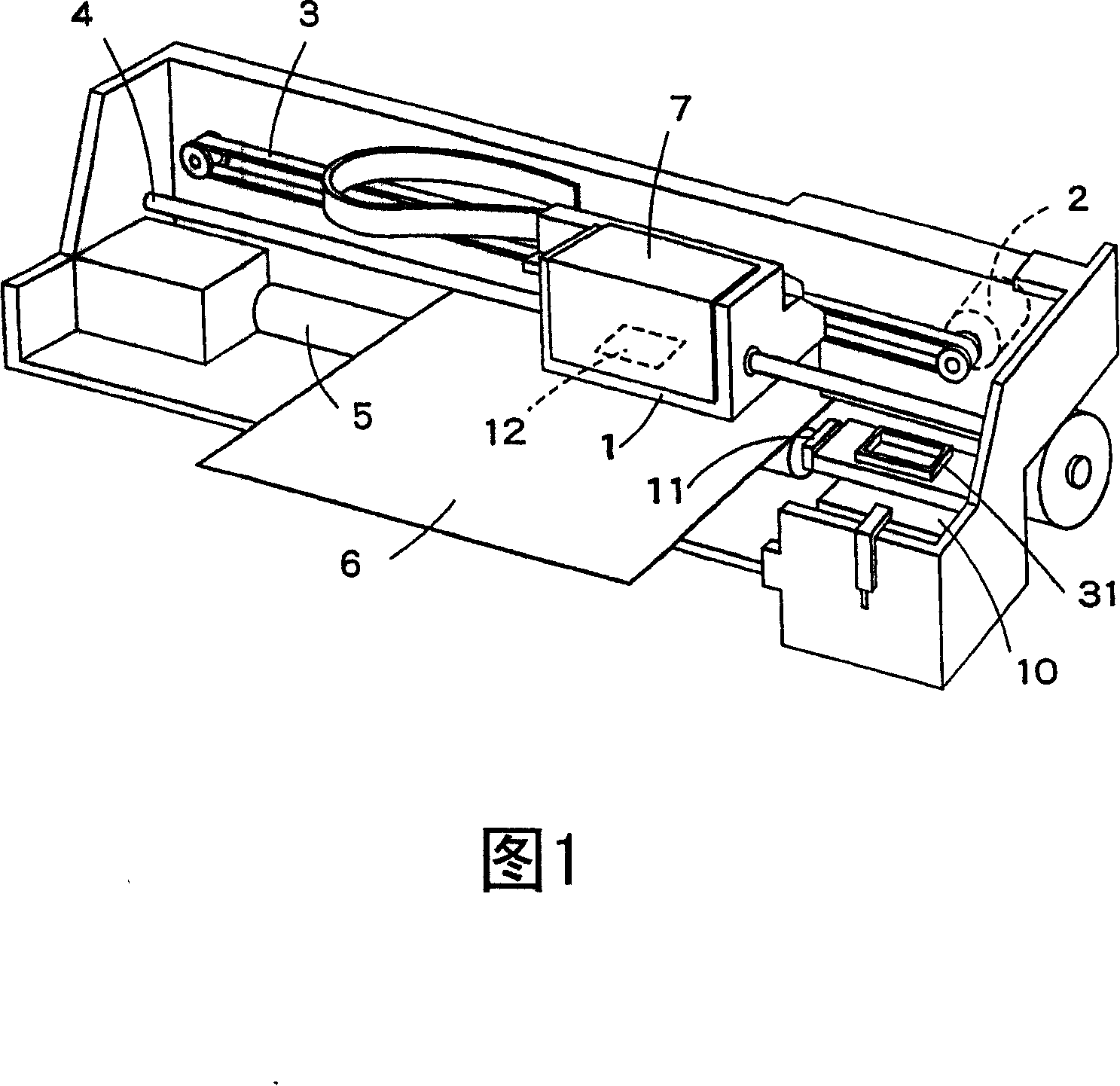
[0089] Fig. 1 shows the schematic structure of the inkjet type recording device (liquid ejection device) using the ink cartridge of this embodiment, and the numeral 1 in Fig. And it is guided by the guide member 4 to reciprocate in the axial direction of the drum 5 .

[0090] An inkjet type recording head 12 is mounted on the side of the carriage 1 facing the recording paper 6 , and an ink cartridge 7 for supplying ink to the recording head 12 is detachably attached to the upper portion thereof.

[0091] In the non-printing area of ​​the recording device, that is, at the home position (right side in the figure), a cover member 31 is arranged. When the recording head loaded on the carriage 1 moves to the home position, the cover member 31 covers the recordi...


PUM


Abstract

A first electrode (46) has a body portion (46a) covering substantially the whole of the area of a recess portion (43), and the body portion (46a) includes a cutout portion (46c). A piezoelectric layer (47) has a body portion (47a) with a diameter smaller than that of the recess portion (43), the entire part of the layer is within the recess portion area, and substantially the whole of the body portion (47a) except the portion corresponding to the cutout portion (46c) is layered over the first electrode (46). An auxiliary electrode (48) extends from the outside up to the inside of the recess portion area, and portion of the auxiliary electrode is positioned inside the cutout portion (46c) of the first electrode (46) and supports portion of the piezoelectric layer (47). A second electrode (49) has a body portion (49a) layered over the piezoelectric layer (47) and an extending portion (49b) extending from the body portion (49a) and connected inside the recess portion area to the auxiliary electrode (48). Condition of residual vibration of a vibrating portion of the liquid-detecting device can be easily and reliably detected, and cracks in the piezoelectric layer can be prevented from occurring.

Description

technical field [0001] The invention relates to a liquid detection device and a liquid container equipped with the device, in particular to a liquid detection device suitable for detecting the remaining liquid in a liquid injection device and a liquid container equipped with the device. Background technique [0002] A typical example of a conventional liquid ejecting device is an ink jet recording device equipped with an ink jet recording head for image recording. Other liquid jetting devices can be exemplified, for example: a device equipped with a colored material ejection head used in the manufacture of color filters such as liquid crystal displays; A device equipped with a nozzle for the electrode material (conductive paste) used; a device equipped with a nozzle for living organisms used in biochip manufacturing; a device equipped with a sample nozzle as a precision bulb, etc. [0003] In an inkjet type recording apparatus that is a representative example of a liquid ej...

Claims


Application Information

Patent Timeline
IPC IPC(8): G01F23/22B41J2/175
Inventor 高桥智明片仓孝浩品田聪
Owner SEIKO EPSON CORP
Why Eureka
Try Eureka