Light-emitting diode

A technology of light-emitting diodes and light-emitting chips, applied in electrical components, piezoelectric/electrostrictive/magnetostrictive devices, circuits, etc., can solve problems such as unbalanced energy distribution and non-adjustable divergence angles, and achieve changes in divergence angles, The effect of increasing the divergence angle

Inactive Publication Date: 2008-03-26
HONG FU JIN PRECISION IND (SHENZHEN) CO LTD +1
View PDF5 Cites 0 Cited by
  • Summary
  • Abstract
  • Description
  • Claims
  • Application Information

AI Technical Summary

Problems solved by technology

[0004] In order to overcome the problems in the prior art that the divergence angle of the light-emitting diode cannot be adjusted and its energy distribution is uneven, the present invention provides a light-emitting diode with an adjustable divergence angle and a relatively balanced divergence energy in all directions

Method used


Image

  • Light-emitting diode
  • Light-emitting diode
  • Light-emitting diode

Examples


Embodiment Construction

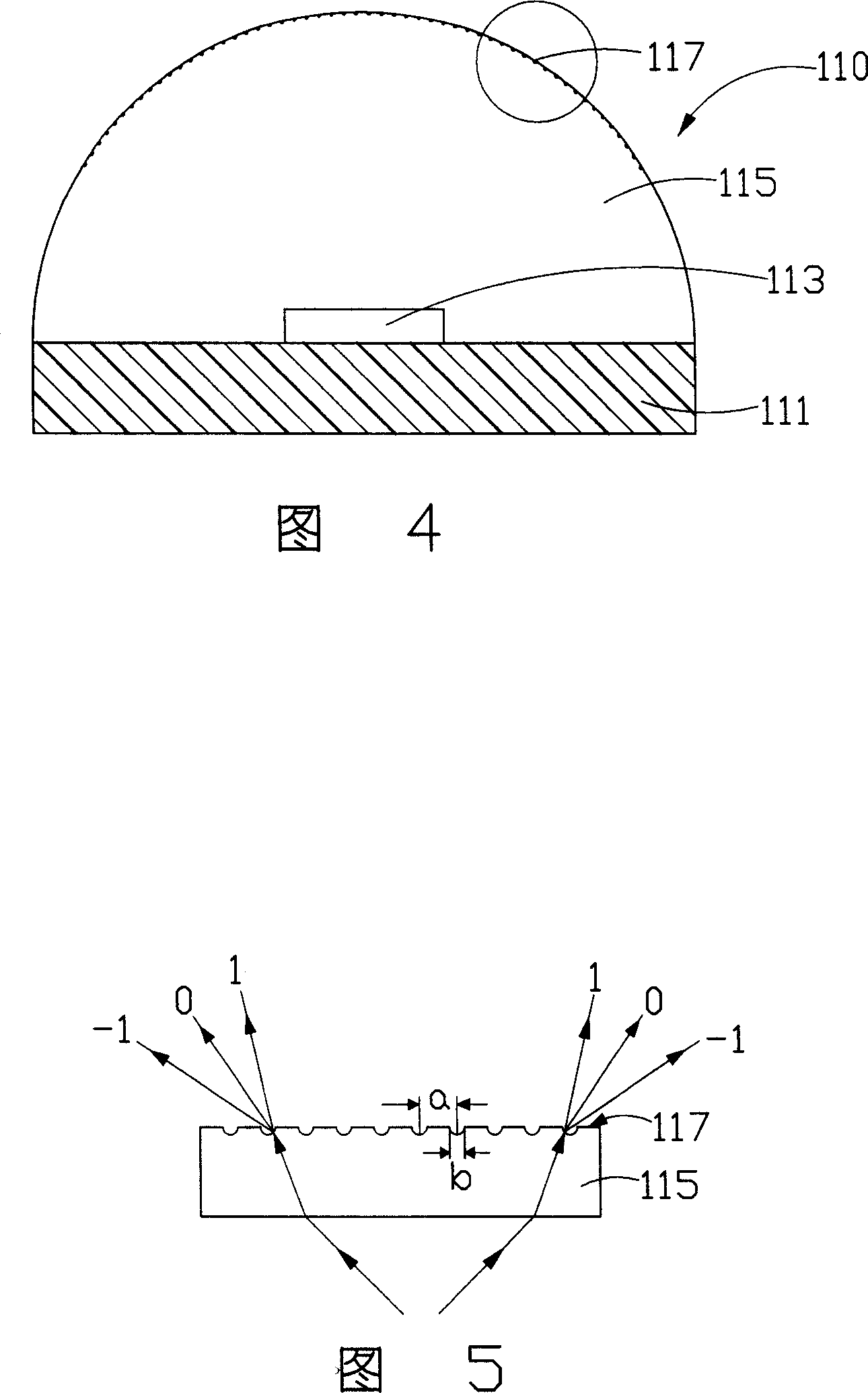
[0012] FIG. 4 is a schematic cross-sectional view of the LED 110 of the present invention. The light emitting diode 110 includes a substrate 111 , a light emitting chip 113 and a packaging structure 115 . The encapsulation structure 115 is used to cover the light-emitting chip 113 and form a light exit surface (not shown), the light exit surface is a curved surface structure, which has the effect of a lens, and the light emitted by the light-emitting chip 113 exits through the light exit surface. A diffraction grating 117 having a plurality of diffraction grating units is continuously arranged on the light exit surface. The diffraction grating 117 is disposed on the light emitting surface, and its distribution area is within the range of the packaging structure 115 irradiated by the light emitting from the light emitting chip 113 . The packaging structure 115 is made of a transparent piezoelectric material, which can be transparent piezoelectric ceramics or polyvinylidene flu...


PUM


Abstract

A luminous LED including a base plate, a luminous chip and a package structure. The luminous chip is on the base plate, the package structure coasts the luminous chip and forms a luminous existence face; a radiating grid is set on the luminous existence face; the package structure is made of transparent piezoelectric materials and an extra circuit controls its mechanical deformation.

Description

【Technical field】 [0001] The present invention relates to a light emitting diode. 【Background technique】 [0002] Light Emitting Diode (LED) has the advantages of power saving, high brightness and long service life, so its products are widely used in mobile phone backlight modules, outdoor large image display billboards, car brake lights and interior lighting, etc. , and its applications are spread across the fields of information, communications, lighting and consumer electronics. The structure of the light emitting diode can be referred to FIG. 1 , the light emitting diode 1 includes a substrate 16 and a light emitting chip 13 , the light emitting chip 13 is fixed on the substrate 16 and covered by the encapsulation structure 15 . The encapsulation structure 15 uses transparent epoxy resin as an encapsulation material. Epoxy resin has the characteristics of excellent adhesion, electrical insulation, heat resistance and chemical stability, shrinkage rate and good mechanic...

Claims


Application Information

Patent Timeline
Patent Type & Authority Patents(China)
IPC IPC(8): H01L33/00H01L41/053
Inventor 吕昌岳余泰成陈杰良
Owner HONG FU JIN PRECISION IND (SHENZHEN) CO LTD
Why Eureka
Try Eureka