Deflecting coil for cathode ray tube and its manufacture method

A cathode ray tube and deflection yoke technology, applied in the field of deflection yoke, can solve the problems of reducing the deflecting coil's ability to resist external environmental interference, defects in volume, weight, display speed and accuracy, and the inability to fully meet the deflecting coil requirements, and improve the The ability to resist external environmental interference, superior performance, light weight effect

Inactive Publication Date: 2008-05-07
中航华东光电有限公司
View PDF2 Cites 0 Cited by
  • Summary
  • Abstract
  • Description
  • Claims
  • Application Information

AI Technical Summary

Problems solved by technology

This kind of material and structure has a large loss
Moreover, there are relatively large defects in terms of volume, weight, display speed and accuracy.
It cannot fully meet the requirements of military airborne and vehicle environments for deflection coils
In addition, the deflection coils in the prior art generally adopt the ordinary mechanical winding method, because the use of polyvinyl acetate-coated wires on the template is mechanically wound and then heat-set, which will destroy the high-temperature heat resistance requirements of the coil.
In this way, supplementary heat protection measures have to be taken, which increases the weight of the structure, and the winding coil cannot be adjusted according to the external environment and processing accuracy, thus reducing the ability of the deflection coil to resist external environmental interference, especially Inductance accuracy can not be guaranteed

Method used


Image

  • Deflecting coil for cathode ray tube and its manufacture method

Examples


Embodiment 1

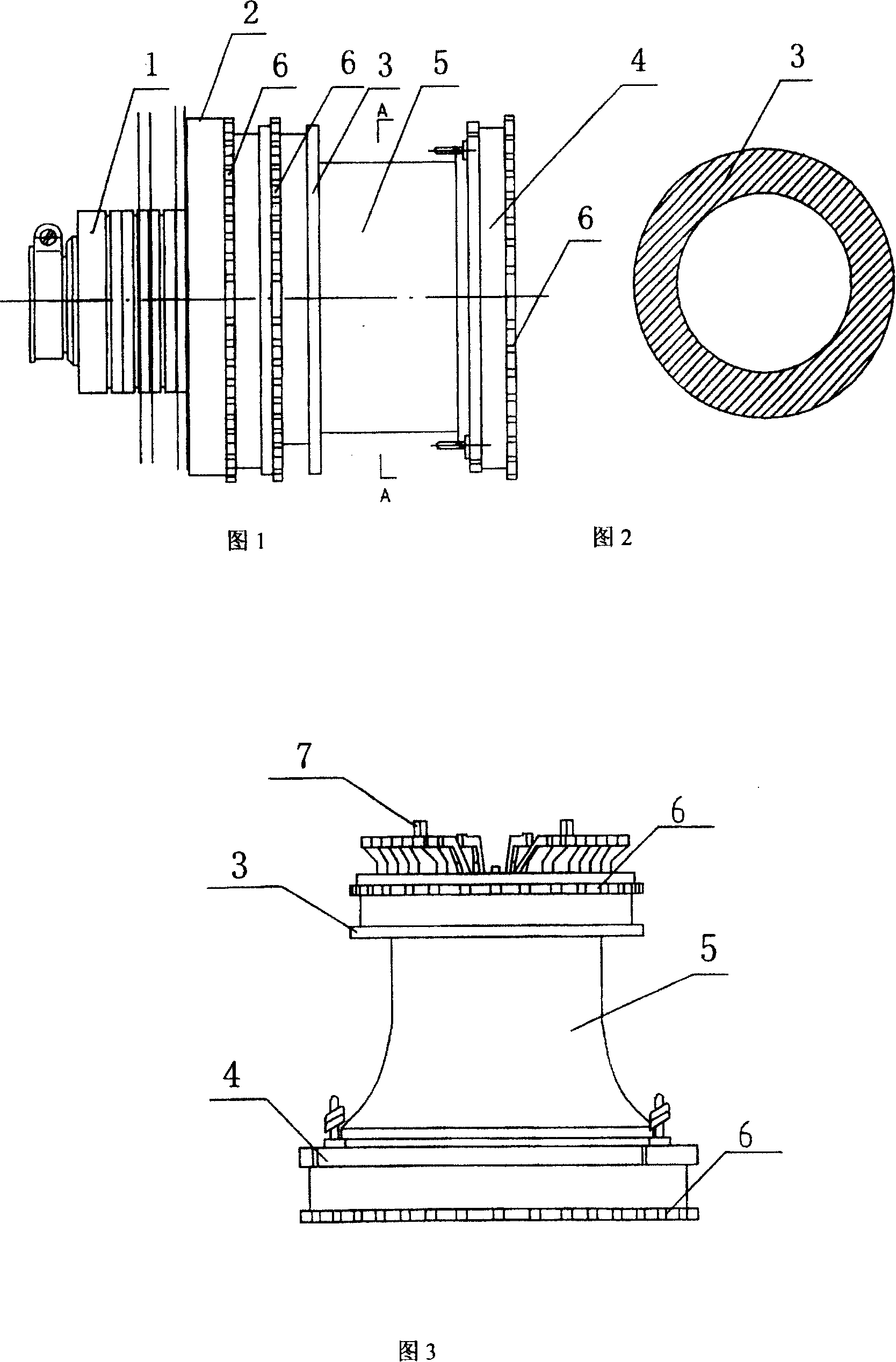
[0023] As shown in FIG. 1 , the deflection yoke includes a magnetic core 5 , a convergence correction component 1 , and insulators 2 , 3 , 4 made of epoxy resin. The magnetic core shown in Figure 2 is a hollow cylinder made of ferrite amorphous alloy strip. The performance parameters of ferrite materials are: initial permeability μ=15000; maximum permeability μm=70000; resistivity ρ(μΩ / cm)=80; Curie temperature T c (℃)=570; Saturation magnetic induction B s (T) = 1.2; residual magnetic induction B r (T)=0.35; coercive force Hc (A / m)=4.

[0024] The magnetic core 5 serves as the loop of the magnetic force line and is also the main supporting part of the deflection coil, and insulating rings are fixed at both ends of the magnetic core. The insulating ring includes an upper ring 4, a middle ring 3, and a bottom ring 2, and the upper ring 4 and the middle ring 3 are fixed on the two ends of the magnetic core 5, and the bottom ring 2 is fixed on the middle ring 3 by connecting t...

Embodiment 2

[0027] As shown in Figure 3, the amorphous alloy used in Example 1 is used to make a combination with a cylindrical shape at one end and a trumpet shape at the other end. After heat treatment, it will be used as the magnetic core 5, and then an insulating ring, epoxy The resin ring includes an upper ring 4, a middle ring 3, and a bottom ring. The upper ring 4 and the middle ring 3 are fixed on both ends of the magnetic core 5. The bottom ring is provided with tooth holes, and the middle ring 3 is provided with matching connecting teeth 7. The bottom ring It is fixed on the middle ring 3 through the connecting teeth 7 on the middle ring 3 . The upper ring 4 of the insulating ring is installed on the horn end of the magnetic core 5 , and the tooth-shaped epoxy resin ring 6 as described in Embodiment 1 is set on the upper ring 4 and the middle ring 3 . The line coil is wound on the upper ring and the middle ring, and the field coil is wound on the upper ring and the bottom ring; ...


PUM


Abstract

Deflecting coil of cathode ray tubes includes magnetic core, wire windings and convergence correction module. Characters are that magnetic core in tubular type hollow hole is made from amorphous alloy. Comparing with products in intraclass, the new type of deflecting coil possesses features of reduced volume 1 / 2, weight 2 / 3, and raising deflection efficiency to 2 times. Moreover, the deflecting coil has high mechanical intensity and high symmetry. Integral magnetic core wraps outside of deflecting coil so as to shield leakage of magnetic field of coil, satisfying requirement of compatible electromagnetic field.

Description

technical field [0001] The technical solution to be protected by the present invention belongs to the technical field of deflection system of cathode ray tube. Background technique [0002] As the core component of the color display tube - deflection coil, because it is connected in the drive scanning circuit, it is a circuit element, its inductance, resistance and frequency characteristics determine the working scanning mode of the display, and it is also an important Electron optical components determine the movement of the electron beam on the screen, which is reflected in the geometric distortion of the display screen, the resolution of characters, the sensitivity of deflection and the nonlinearity of graphics. It can be said that if the display tube is compared to the eyes of the avionics system, then the quality of a coil is directly related to the clarity of the eye and the quality of the displayed image. [0003] Moreover, in order to speed up the display speed of i...

Claims


Application Information

Patent Timeline
Patent Type & Authority Patents(China)
IPC IPC(8): H01J29/76H01J9/236
Inventor 吴华夏方卫邱祚良夏丽梅金兴隆何宏玉徐虎袁烨胡海城苏靖吴磊黄敦锋
Owner 中航华东光电有限公司
Why Eureka
Try Eureka