Method and device of heavy oil two stage catalytic cracking reforming and gasoline upgrade coupling

A catalytic cracking and heavy oil technology, applied in the petroleum industry, processing hydrocarbon oil, etc., can solve the problem of underutilization of gasoline reaction, and achieve the effects of inhibiting thermal cracking reaction, reducing losses, and improving the ratio of agent to oil.

Inactive Publication Date: 2008-06-11
石宝珍
View PDF6 Cites 0 Cited by
  • Summary
  • Abstract
  • Description
  • Claims
  • Application Information

AI Technical Summary

Problems solved by technology

In the prior art, these characteristics of gasoline reaction have not been fully utilized

Method used


Image

  • Method and device of heavy oil two stage catalytic cracking reforming and gasoline upgrade coupling
  • Method and device of heavy oil two stage catalytic cracking reforming and gasoline upgrade coupling
  • Method and device of heavy oil two stage catalytic cracking reforming and gasoline upgrade coupling

Examples


Embodiment 1

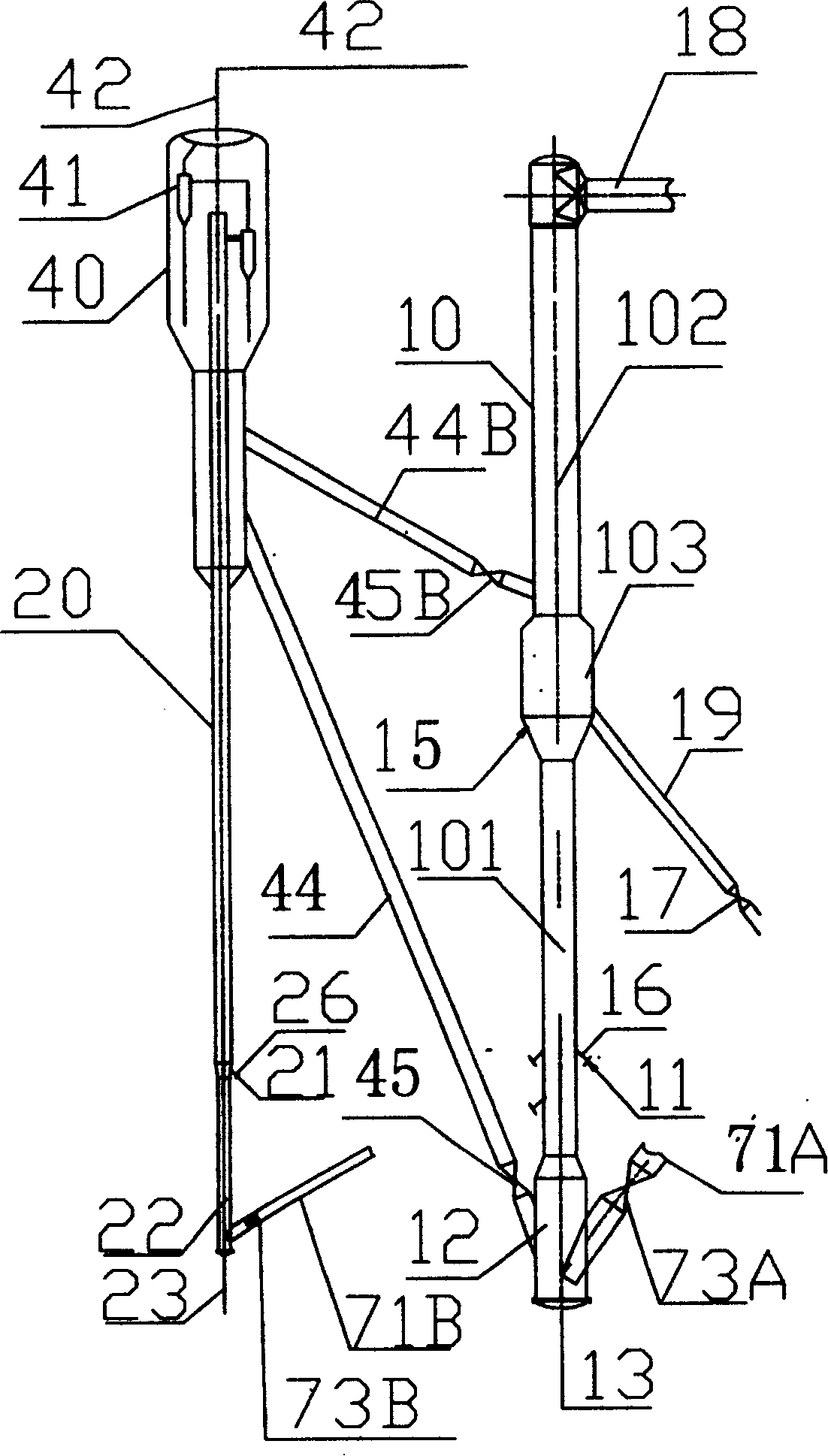
[0029] Example 1. A device for the coupling of heavy oil two-stage catalytic cracking conversion and gasoline upgrading, including a heavy oil reactor 10 and a gasoline reactor 20. The heavy oil reactor 10 includes a cracking reaction section 101 connected in series from bottom to top, and a gas-solid separation section. 103 and upgrading reaction section 102, the cracking reaction section 101 and upgrading reaction section 102 of the heavy oil reactor 10 both adopt the riser type. 11 is feedstock oil, 16 is feedstock oil inlet, 12 is catalyst mixing and pre-lifting section, 13 is catalyst lifting medium, 18 is outlet pipe of heavy oil reactor, 71A, 71B are regeneration standpipes, 73A, 73B are regeneration slide valves. The gasoline reactor 20 adopts a riser type, and a catalyst delivery pipe 44B is installed between the gasoline reaction settler 40 at the outlet and the reforming reaction section 102 of the heavy oil reactor 10, and 45B is a catalyst slide valve after the gas...

Embodiment 2

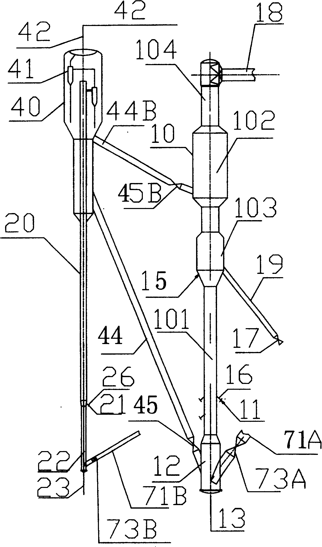
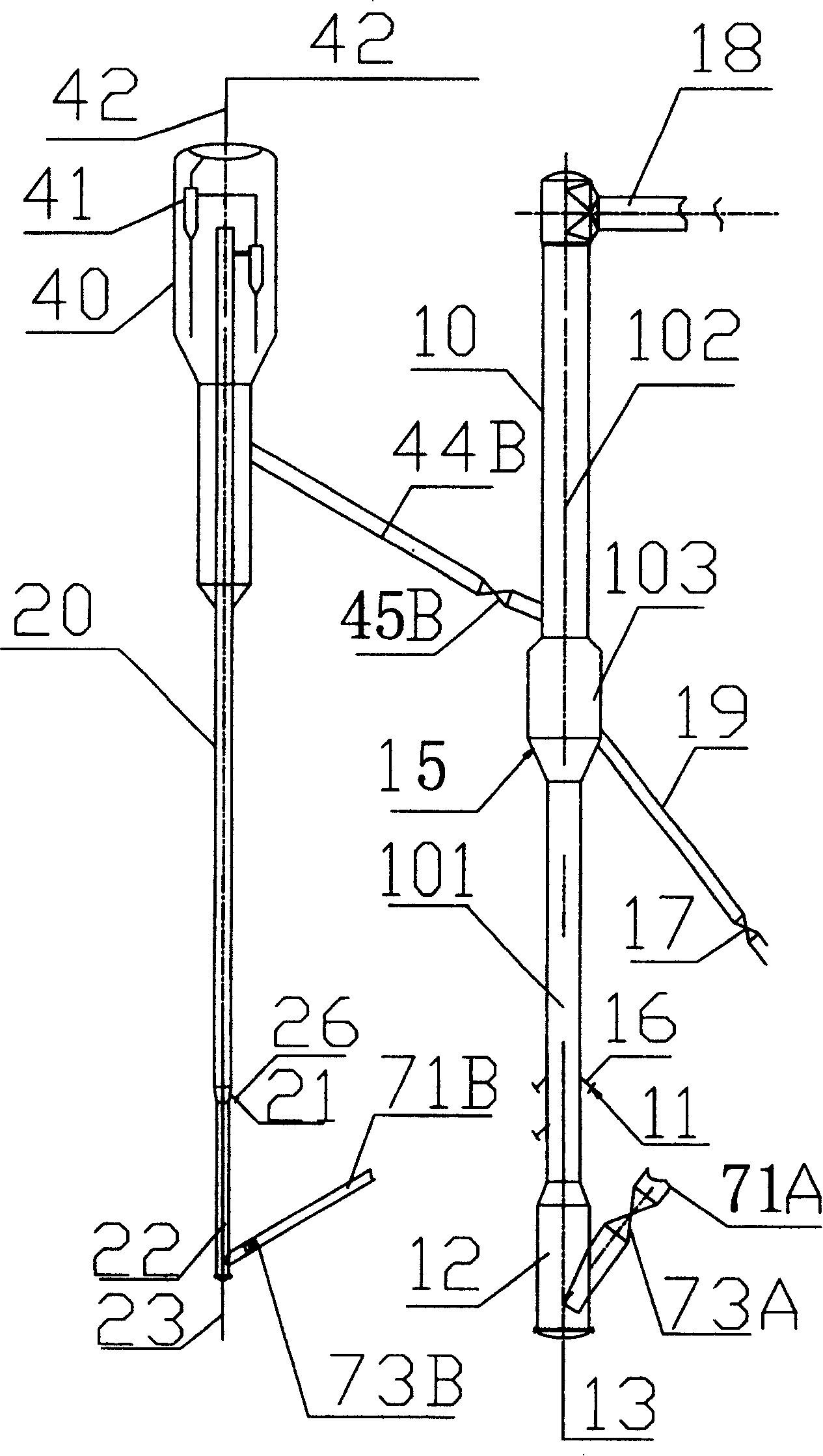
[0033] Example 2. In this example, the schematic diagram of the device structure of heavy oil two-stage catalytic cracking conversion and gasoline upgrading coupling is shown in Figure 4 , the structural diagram of the anti-re-device is shown in Figure 5 . The difference with the device in Example 1 is that a catalyst return pipe 24 and 25 are slide valves between the gasoline settler 40 and the bottom of the gasoline reactor 20; a catalyst delivery pipe is arranged between the gasoline settler 40 and the bottom of the heavy oil reactor 10 44. During use, the slide valve 45 on the delivery pipe is closed.

[0034] The reaction materials are: Daqing atmospheric heavy oil, 100t / h heavy oil, gasoline feed is catalytic gasoline from other devices, 40t / h; heavy oil is preheated at 220°C, gasoline is at 40°C; heavy oil reactor feedstock oil and recycled oil are mixed into four routes Entering the riser of the first reaction zone, gasoline enters the reactor in two ways; the rea...


PUM


Abstract

The invention is a two-stage heavy oil catalytic cracking conversion method and device, belonging to petroleum refining process and device technical field, separating heavy oil reaction course into top and bottom reacting regions, making raw oil and regenerated catalyst firstly contact and react with each other in the bottom reacting region and successively separating the carbon deposit deactivated catalyst from reacting oil; making the oil gas go up into the second reacting region to mix with the catalyst used in gasoline reaction and continue reaction; a heavy oil reactor is connected in parallel with gasoline reacting part; the gasoline and catalyst complete reaction in the gasoline reactor and then make gas-solid separation in gasoline settler, where the oil gas is discharged through pipeline and the extracted catalyst is fed into pre-rising stages below the first and second heavy oil reacting regions to continue taking part in heavy reaction; a catalyst return pipe is arranged between the pre-rising stages of the gasoline settler and gasoline reactor to make a part of catalyst used in gasoline reaction return to the bottom of the gasoline reactor, so as to take part in gasoline reaction. And it can obviously raise efficiency of heavy oil reactor, improve product quality and need not consume energy because of catalyst change.

Description

technical field [0001] The invention belongs to the technical field of petroleum refining technology and equipment, and in particular relates to a method and device for two-stage catalytic cracking conversion of heavy oil and gasoline upgrading coupling. Background technique [0002] Catalytic cracking is the most important processing device for heavy petroleum fractions (including vacuum wax oil, coker wax oil, atmospheric press oil, vacuum press oil, etc.), and is the production device of 80% gasoline in China. The catalytic cracking reaction uses a riser reactor, and the reaction raw materials enter at the bottom of the riser. Under the catalyst environment, the reaction is carried out at an average flow rate of about 15m / s and a temperature of about 500 degrees. The reaction time is generally about 3s. The length of the riser is 30-40 meters. Because about 7-10% of the raw materials in the reaction process will be converted into coke, these cokes will adhere to the surf...

Claims


Application Information

Patent Timeline
Patent Type & Authority Patents(China)
IPC IPC(8): C10G57/00
Inventor 石宝珍
Owner 石宝珍
Why Eureka
Try Eureka