Solar energy high-temperature vacuum heat collection tube

A high-temperature vacuum and solar energy technology, which is applied in the field of solar thermal utilization, can solve the problems of Kovar alloy sealing process complexity, high cost, and vacuum failure, and achieve the effects of low cost, strong practicability, and improved reliability

Inactive Publication Date: 2008-06-25
张耀明 +2
View PDF7 Cites 2 Cited by
  • Summary
  • Abstract
  • Description
  • Claims
  • Application Information

AI Technical Summary

Problems solved by technology

[0005] In previous studies, the applicant also designed a technical solution using Kovar alloy sealing, but after practice and further research, it was found that the technical solution containing Kovar alloy sealing structure has the following shortcomings: First, due to the use of Kovar alloy sealing The Kovar alloy sealing process is complex and the cost remains high; second, the glass tube and the Kovar alloy seal are prone to cracking or vacuum failure due to stress and other reasons

Method used


Image

  • Solar energy high-temperature vacuum heat collection tube
  • Solar energy high-temperature vacuum heat collection tube
  • Solar energy high-temperature vacuum heat collection tube

Examples


Embodiment 1

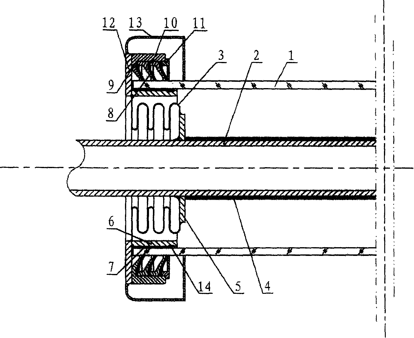
[0018] The structure of this embodiment is as figure 1 As shown, the solar high-temperature vacuum heat absorbing tube includes a glass sleeve 1, a heat-absorbing metal tube 2 coaxially installed inside the glass sleeve, and a corrugated compensator 3 between the two. The heat-absorbing metal pipe is coated with a high-temperature selective absorption coating 4, and there is a vacuum layer between the glass sleeve 1 and the heat-absorbing metal pipe 2, and the inner flange 5 sealed and welded to it is passed near the end of the heat-absorbing metal pipe 2 It is sealed and welded with one end of the corrugated compensator 3 (obviously, it is also feasible to directly seal and weld with one end of the corrugated compensator near the end of the heat-absorbing metal tube), and the transition between the other end of the corrugated compensator 3 and the glass sleeve 1 The ends of the metal tube 6 are sealed and welded, and the transition metal tube 6 and the glass casing 1 are nest...

Embodiment 2

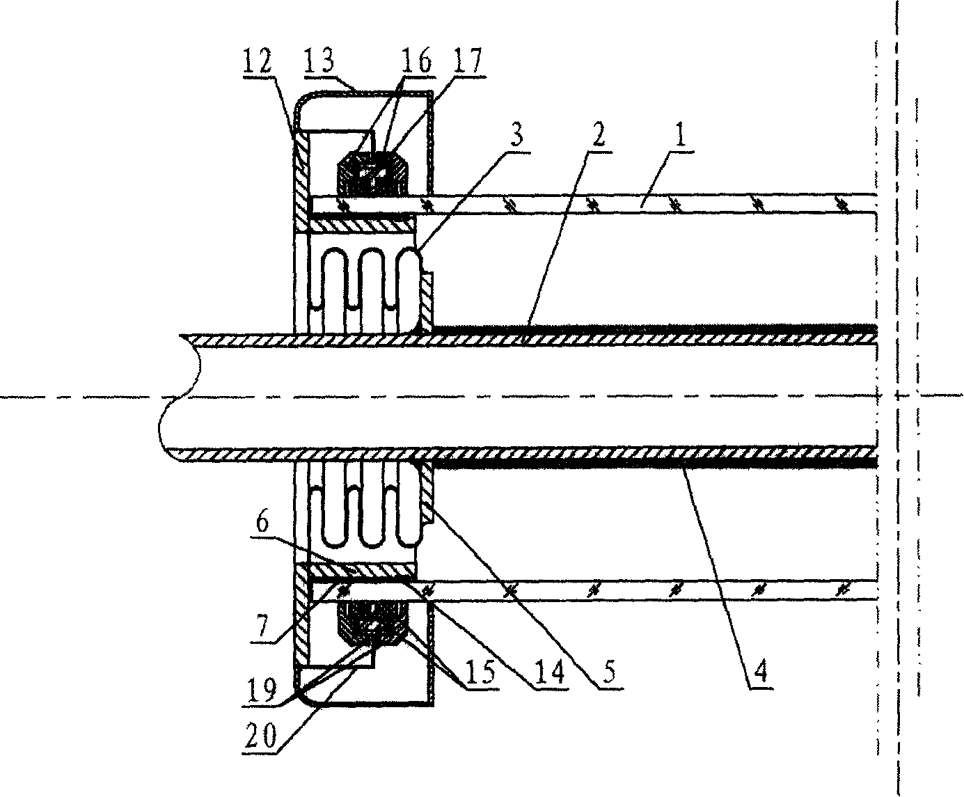
[0026] Such as figure 2 As shown, the basic structure of this embodiment is the same as that of Embodiment 1, the main difference is: the inner edge of the turned back casing 20 welded and fixed with the flange cover 12 and the outer circle of the metal pipe 17 with a "T" cross-section in the axial direction Welding, the metal tube 17 is set outside the glass casing 1, and the vacuum seals are two wedge-shaped vacuum seal rings 15, which are respectively clamped in the depressions on both sides of the metal tube 17, and the pressing parts are made of conical, rectangular or arc-shaped These two nuts 16 are relatively screwed on the external thread of the metal pipe 17, and the two nuts 16 are respectively pressed against the exposed parts of the two wedge-shaped vacuum sealing rings 15 to form a reliable second seal (actual design , metal tube circumferential section is " L " shape, only a wedge-shaped vacuum sealing ring 15 is adorned, and it is obviously also feasible to co...

Embodiment 3

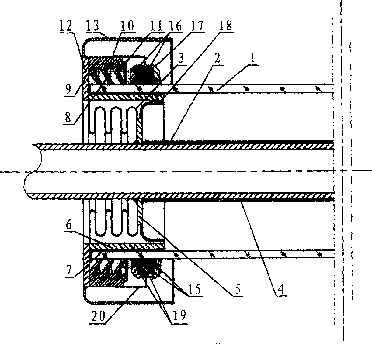
[0028] Such as image 3As shown, Embodiment 3 is essentially a combination of Embodiment 1 and Embodiment 2. The vacuum seal is composed of a cup 8 and a wedge-shaped vacuum seal 15. Other structures such as the cup 8 and the pressing parts of the vacuum seal 15 can be See descriptions of Examples 1 and 2. The metal pipe 17 with a "T" cross-section and the housing 9 supported by the leather cup 8 are connected by transition welding through the shell sleeve 20 .

[0029] In order to ensure the long-term sealing strength between the glass sleeve and the transition metal tube, the heat-resistant radiation cover 18 is welded on the inner flange 5 so that the seal is not subject to high-temperature internal heat radiation of the heat-absorbing metal tube 2, thereby blocking the radiation of the heat-absorbing metal tube Heat damages the seal. In this way, the sealing part is always in a relatively low temperature state, and the bonding part is protected to the greatest extent.


PUM


Abstract

The invention relates to a solar energy high temperature vacuum heat adsorption tube, belonging to the solar energy utilization technique. The invention comprises a glass tube, a heat adsorption metallic tube coaxially mounted inside the glass tube, and a ripple compensator between them. Wherein, the end of heat adsorption metallic tube is sealed welded with one end of ripple compensator via the inner flange disc; another end of ripple compensator is sealed welded with the end of transition metallic tube; the inner wall of transition metallic tube is sealed adhered with the glass tube to form the first seal; the transition metallic tube is sealed welded with a flanged structure which covers the outer wall of glass tube; the connection between the flanged structure and the outer wall of glass tube is mounted with a vacuum sealing element and a compressing element; and the compressing element via the connection with the flanged structure can compress the vacuum sealing element on the outer wall of glass tube to form the second seal. The invention has simple process, lower cost and strong practicability, while it can improve the development of slot solar energy collection technique.

Description

technical field [0001] The invention relates to a solar high-temperature heat-absorbing tube, in particular to a high-temperature vacuum heat-absorbing tube that can be used in a trough-type solar thermal power generation system, and belongs to the technical field of solar light and heat utilization. Background technique [0002] Since the 20th century, fossil fuels have been continuously consumed, their reserves have been depleted, and environmental pollution has become increasingly serious. The overall human demand for nature and the amount of pollutant emissions have exceeded the earth's capacity as early as around 1980. People are increasingly eager to develop and utilize new energy sources, and the continuous development of new technologies such as solar thermal power generation and photovoltaic power generation provides a strong guarantee for solving various existing technical problems. Most developing countries, especially those with dense population, are rich in sola...

Claims


Application Information

Patent Timeline
Patent Type & Authority Patents(China)
IPC IPC(8): F24J2/46
CPCY02E10/40
Inventor 张耀明孙利国张振远张文进刘晓晖王军
Owner 张耀明
Why Eureka
Try Eureka