Radiator valve

A technology of heating body and shell, applied in heating mode, lighting and heating equipment, lift valve, etc., can solve problems such as changing valve performance

Inactive Publication Date: 2008-07-02
DANFOSS AS
View PDF8 Cites 0 Cited by
  • Summary
  • Abstract
  • Description
  • Claims
  • Application Information

AI Technical Summary

Problems solved by technology

However, the use of an additional sealing ring has the disadvantage of changing the performance of the valve, especially when a new sealing ring is used, resulting in hysteresis, since the push rod has to overcome the frictional force on the two sealing rings

Method used


Image

  • Radiator valve
  • Radiator valve

Examples


Embodiment Construction

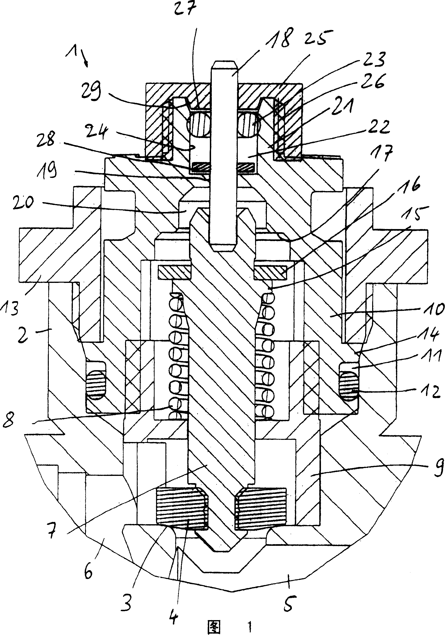
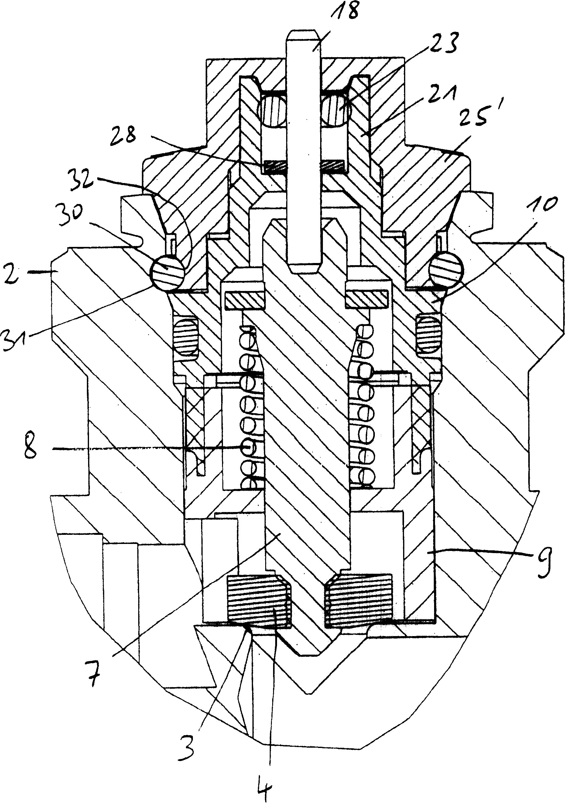
[0027] A heater valve 1 has a housing 2 in which a valve seat 3 is arranged and a valve element 4 cooperates with the valve seat 3 . The valve element 4 together with the valve seat 3 forms a fluid flow control for a heat transfer medium fluid from an inlet 5 to an outlet 6 . Furthermore, the amount of fluid flowing through depends on the distance between the valve element 4 and the valve seat 3 .

[0028] The valve element 4 is held on a valve stem 7 which is prestressed in the opening direction by a spring 8 . The spring 8 is supported here on an insert 9 which is arranged in the housing 2 .

[0029] A cup-shaped housing part 10 covers the insert part 9 and rests in a gap 11 between the housing 2 and the insert part 9 . The housing part 10 is sealed here by a seal 12 . The housing part 10 is fastened in the housing 2 via a sleeve 13 , the sleeve 13 being screwed into the housing 2 and engaging a surrounding projection 14 of the housing part 10 .

[0030]The valve stem 7 ...


PUM


Abstract

A radiator valve (1) with a fluid passage control device in a housing (2), said control device having a movable element (4, 7), which can be actuated by a tappet (18) that is guided through an opening (19) in a housing part (10) of the housing (2) and is provided with a sealing arrangement. It is desired to facilitate reliable operation over a relatively long period. For this purpose, the sealing arrangement has only one seal (23) co-operating with the tappet (18), this seal (23) being accessible through a mounting opening in the housing part (10), which opening is covered by a cover (25).

Description

technical field [0001] The invention relates to a heating body valve, which has a fluid flow control mechanism in a housing, the control mechanism has a movable element, which can be actuated by a push rod, the The push rod is guided through an opening in a housing part of the housing and is provided with a sealing system. Background technique [0002] A heater valve controls the flow of heat transfer medium fluid, usually water, through a heater. Thus, a movable valve element is moved more or less violently close to the valve seat, or rests on the valve seat. The valve element is actuated from the outside by means of an adjusting mechanism. The adjustment mechanism can be manually operated. Usually the adjustment mechanism is formed by a thermostat cover. [0003] In order to prevent the heat transfer medium fluid from flowing out of the heating body valve, the push rod seals the housing through a sealing system. Since the sealing system must seal against the moving pu...

Claims


Application Information

Patent Timeline
Patent Type & Authority Patents(China)
IPC IPC(8): F16K1/00F16K41/04F16K27/02F16K27/12F16K1/36F16K1/46F16K31/64F16K41/18F16K43/00F24D19/10
CPCF16K1/46F16K43/008F16K27/12F16K41/04F16K1/36F16K1/00
Inventor P·赫尔克A·马克瓦特T·V·克罗
Owner DANFOSS AS
Why Eureka
Try Eureka