
Method for checking software edition in programmable logic element

A software version and programming logic technology, applied in the field of electronics or communication, can solve the problems of software version can not be verified, low reliability, etc., to achieve software version verification and upgrade, reduce dependencies, and improve verification reliability. Effect

Inactive Publication Date: 2008-07-30
HUAWEI TECH CO LTD
View PDF4 Cites 0 Cited by
  • Summary
  • Abstract
  • Description
  • Claims
  • Application Information

AI Technical Summary

Problems solved by technology

[0009] The present invention provides a method for verifying the software version in a programmable logic device, so as to solve the problems that the reliability of the PLD software version verification of the system in the prior art is low, and the software version cannot be verified in some cases

Method used


Image

  • Method for checking software edition in programmable logic element
  • Method for checking software edition in programmable logic element
  • Method for checking software edition in programmable logic element

Examples


Embodiment Construction

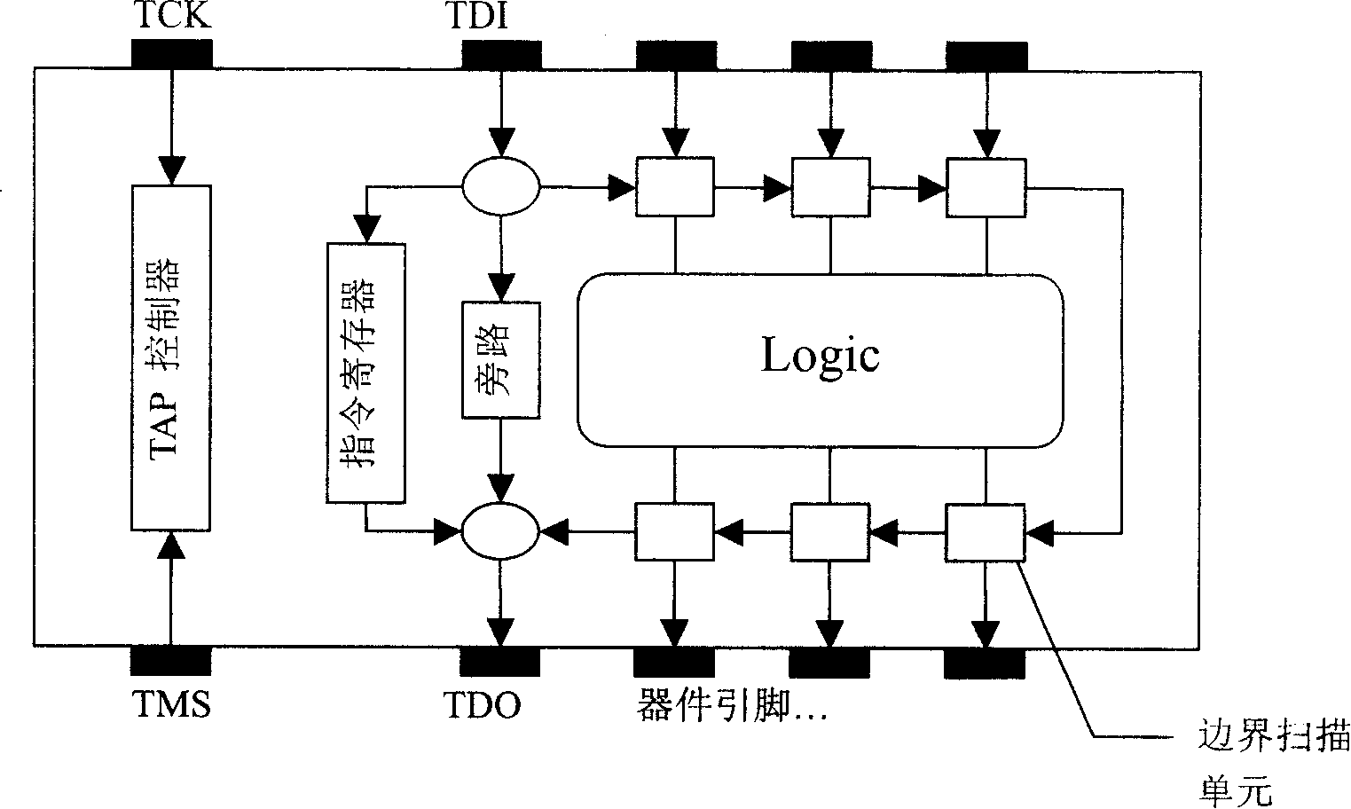
[0026] Boundary-scan testing technology was developed based on the JTAG (Joint Test Action Group) interface as a solution to the PCB physical access problem caused by the increasing crowding of board assemblies due to new packaging technologies. In 1988, some companies in North America jointly established the Joint Test Action Group (JTAG: Joint Test Action Group), which standardized the initial Boundary Scan technology. In 1990, IEEE (Institute of Electrical and Electronic Engineers) accepted the specification as standard 1149.1. Boundary-scan embeds test circuitry at the chip level to form a comprehensive board-level test protocol. Using the boundary-scan industry standard IEEE 1149.1, complex assemblies can be tested, debugged, programmed in-system devices, and hardware problems diagnosed. With access to scan path I / O, the need for physical test points on the board can be eliminated or greatly reduced. In addition to board testing, boundary scan testing allows programming...


PUM


Abstract

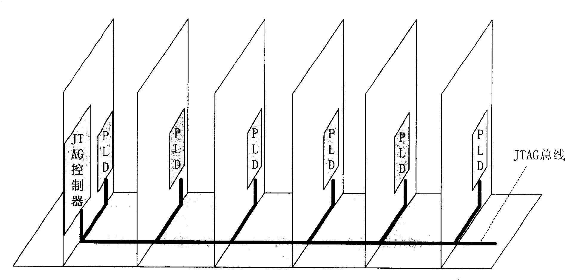
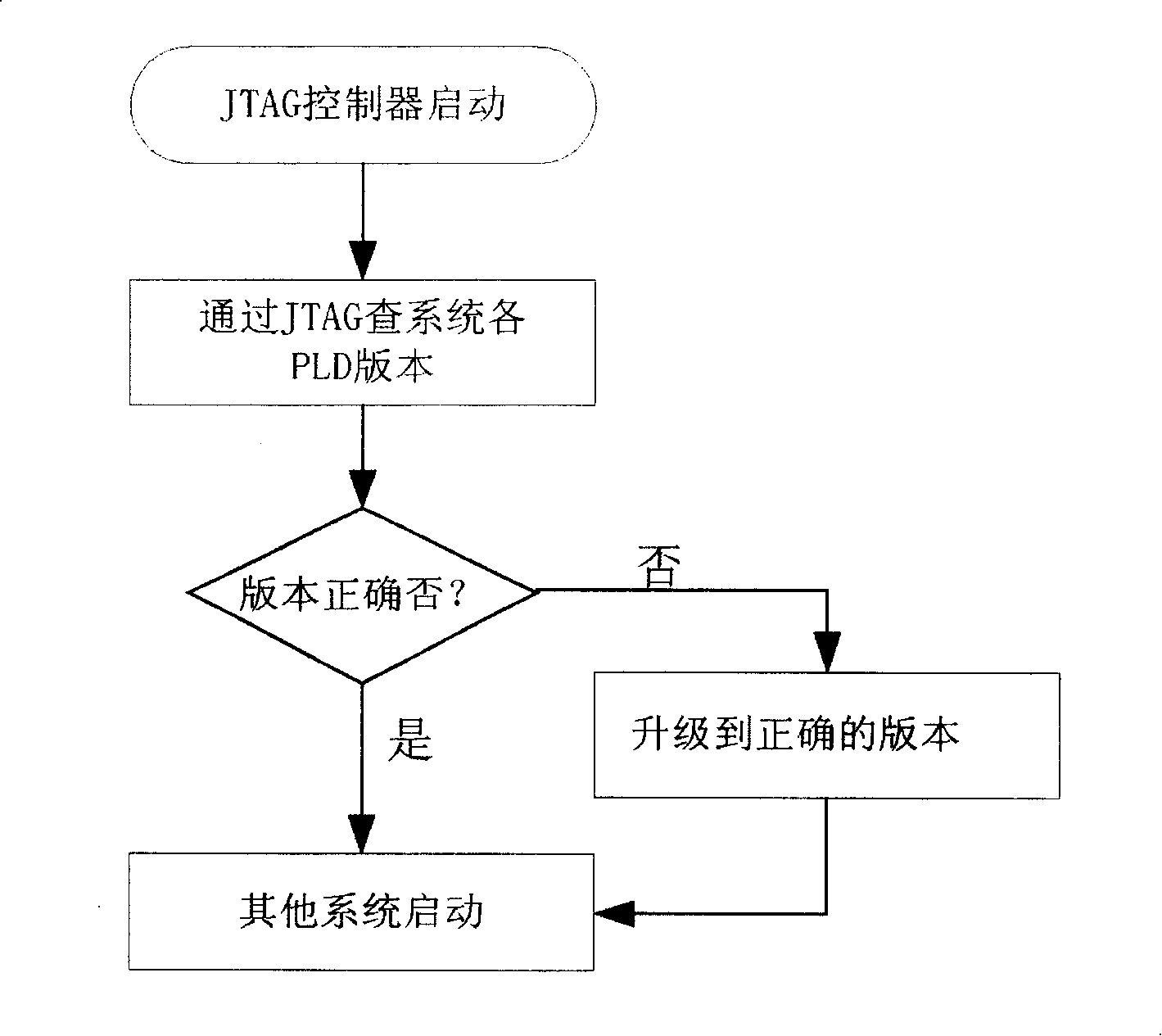
A method for calibrating software version in programmable logic component includes starting up JTAG controller and sampling software version in PLD by said controller, judging whether software version in each PLD has correct corollary relation to system software or not and starting up the rest part of system if it is or otherwise upgrading software version is LPD to be correct version by JTAG controller.

Description

technical field [0001] The invention relates to testing technology in the field of electronics or communication, in particular to a method for checking the software version of a programmable logic device (PLD: Programmable Logic Device). Background technique [0002] With more and more functions in electronic or communication systems, in order to realize the functions, the structure of circuits in electronic or communication systems is becoming more and more complex, and the design of multi-layer boards is becoming more and more common. In the design , a large number of postable programmable logic devices will be used, some of which are used as a part of the control system, and some are distributed on different boards of the system to realize the special functions of the boards. [0003] Since the programmable logic device can realize its function through programming, when the single board in the electronic or communication system needs to add new functions or replace the or...

Claims


Application Information

Patent Timeline
Patent Type & Authority Patents(China)
IPC IPC(8): G06F9/445
Inventor 李占有王重阳王永生
Owner HUAWEI TECH CO LTD
Learn More