Supercharge Your Innovation With Domain-Expert AI Agents!

Continuous firing furnace with treatment unit for exhausted gas

A technology of exhaust gas and processing unit, which is applied in the field of continuous firing furnace, and can solve the problems of high combustion efficiency, pollution of fired product quality, inability to grasp and adjust binder volatiles, etc.

Active Publication Date: 2008-08-06
KOYO THERMO SYST CO LTD
View PDF4 Cites 0 Cited by
  • Summary
  • Abstract
  • Description
  • Claims
  • Application Information

AI Technical Summary

Problems solved by technology

[0005] However, as in the above-mentioned continuous firing furnace, a continuous firing furnace in which an exhaust hole is provided on the furnace wall in a region where the temperature is equal to or higher than the predetermined activation temperature of the catalyst, and a structure for supporting the catalyst is housed inside the continuous firing furnace , because it is difficult to discharge the gas containing the binder volatiles generated from the fired object from the exhaust hole without residue, so there is a gas containing the binder volatiles that contaminates the gas medium in the furnace and makes the fired object The quality of the furnace is deteriorated, and it is condensed on the low-temperature surface in the furnace, and at the same time, it will be emitted from the outlet of the fired product of the continuous firing furnace. In addition, like this continuous firing furnace, the A continuous firing furnace in which a catalyst-carrying structure is built in the exhaust hole and the binder volatiles are burned, there is also the problem of not being able to grasp and adjust the combustion state of the binder volatiles to obtain high combustion efficiency

Method used


Image

  • Continuous firing furnace with treatment unit for exhausted gas
  • Continuous firing furnace with treatment unit for exhausted gas
  • Continuous firing furnace with treatment unit for exhausted gas

Examples


Embodiment Construction

[0018] Embodiments of the present invention will be described in detail below with reference to the accompanying drawings.

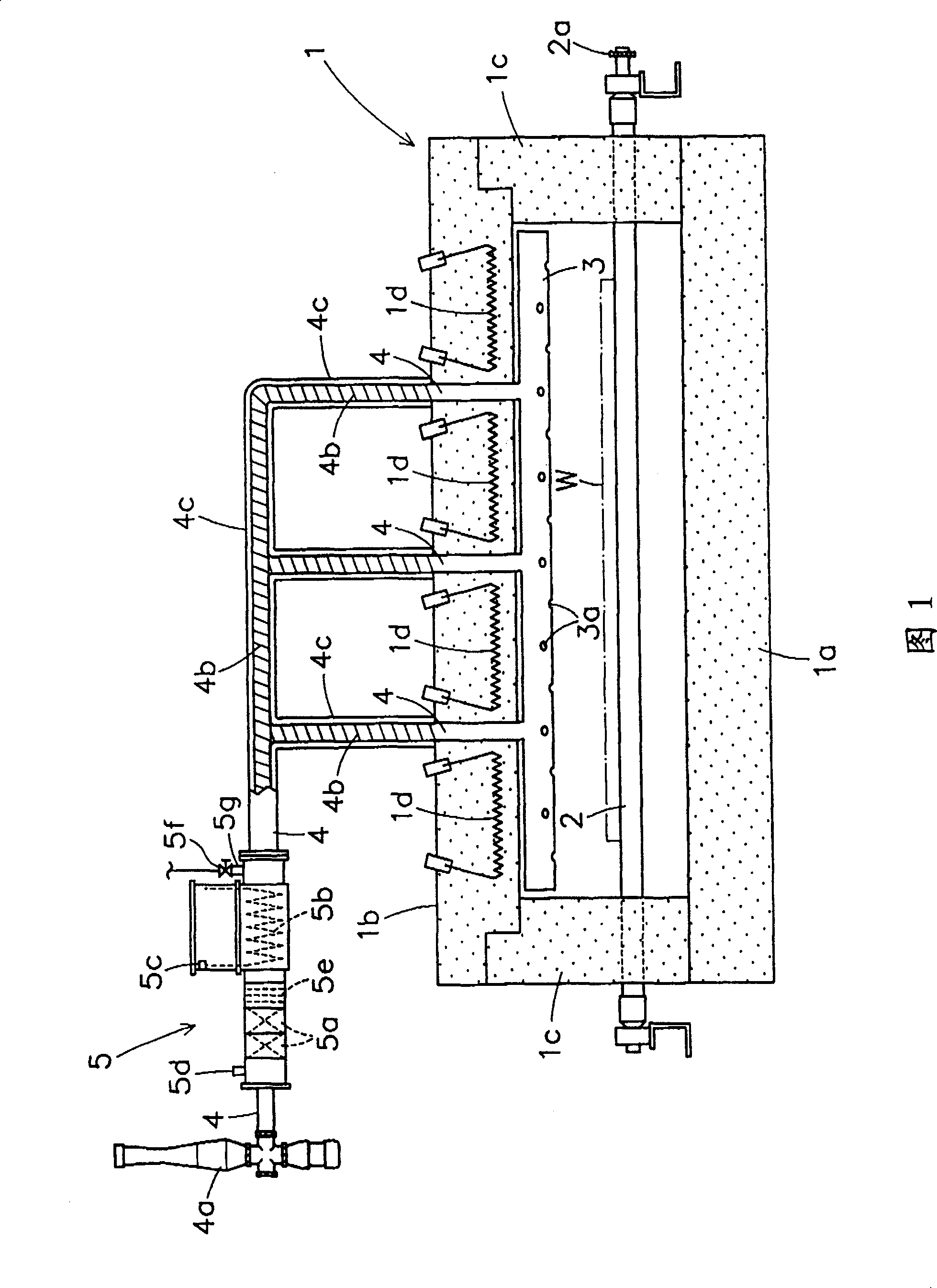
[0019] Fig. 1 is a schematic cross-sectional view showing an embodiment of a continuous firing furnace with an exhaust gas treatment unit according to the present invention.

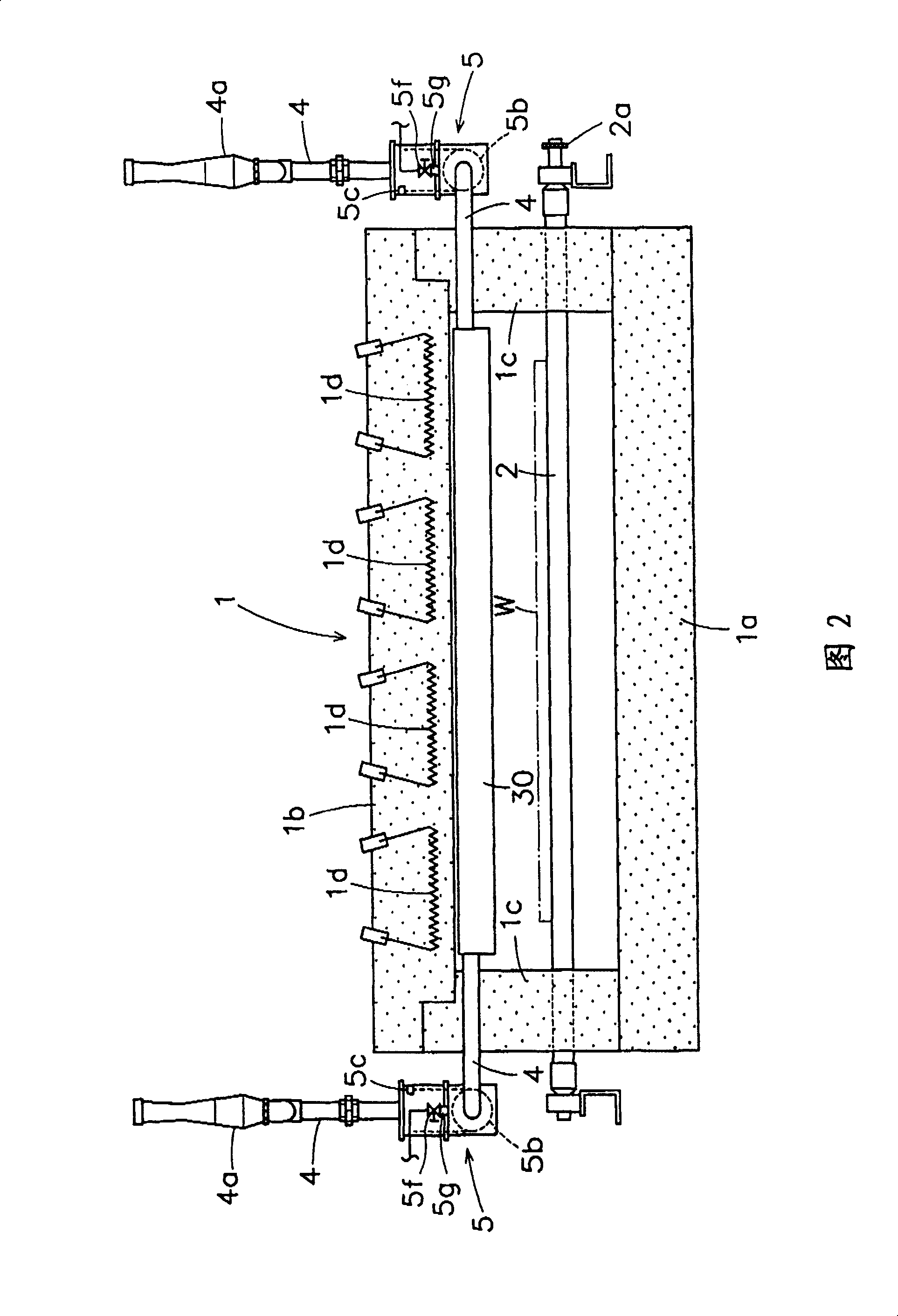
[0020] This continuous firing furnace with an exhaust gas treatment unit is formed of a bottom wall 1a, a top wall 1b, and left and right side walls 1c, 1c made of a thick-walled hard heat insulating material made of vacuum-formed ceramic fibers. The furnace body 1 having a flat rectangular parallelepiped shape is heated inside the furnace body by a plurality of electric heaters 1d embedded in the ceiling wall 1b and the like.

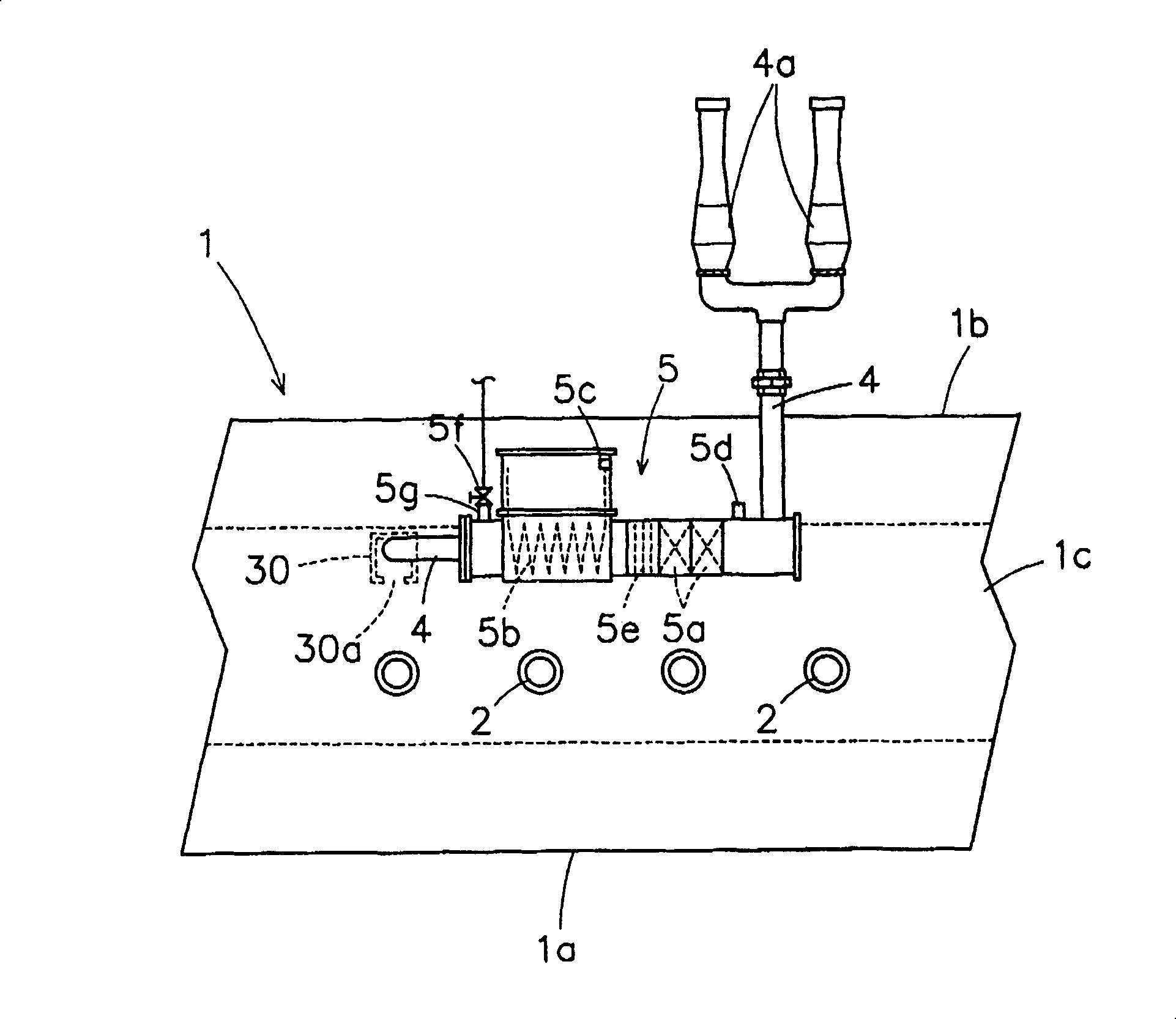
[0021] The furnace body 1 is formed to be long in the front-rear direction (direction perpendicular to the paper surface in FIG. 1 ), and a plurality of conveying rollers 2 are arranged at regular intervals in the front-rear direction, penetrating the furna...


PUM


Abstract

Provided is a continuous kiln with a discharge gas treatment unit for exhausting by oxidizing-decomposing (burning) a binder volatile matter by a catalyst by wholly sucking atmospheric gas in a kiln body including the binder volatile matter generated from a baking object. This continuous kiln with the discharge gas treatment unit is constituted so that a tubular or slender box-shaped gas sucking member 3 for forming a large number of holes 3a or slits over the substantially total length for sucking the gas including the binder volatile matter generated from the baking object W, is arranged in the orthogonal direction to the carrying direction of the baking object W in an upper part in the kiln body 1, or arranged in the parallel direction to the carrying direction of the baking object W in a side part in the kiln body 1; and the discharge gas treatment unit 5 incorporated with a freely ventilable catalyst carrier 5a for carrying the catalyst for oxidizing-decomposing the binder volatile matter, is arranged in the middle of an exhaust pipe 4 derived outside the kiln body 1 from this gas sucking member 4.

Description

technical field [0001] The present invention relates to a continuous firing furnace with an exhaust gas treatment unit for treating gas containing binder volatiles generated from a fired product. Background technique [0002] In a continuous firing furnace for firing a to-be-fired object containing a binder mainly composed of organic matter, the binder is volatilized from the to-be-fired object in the mid-range (range of about 300 to 400° C.) of temperature rise. Since the binder has a bad influence on combustion, the gas (gas medium in the furnace) containing binder volatiles is discharged out of the furnace through the exhaust pipe. However, when the temperature of the exhaust gas decreases in the exhaust pipeline, there are binder volatiles that solidify and adhere to the inner wall of the exhaust pipeline, which will cause damage to the exhaust system of the kiln or the exhaust pipeline of the factory. problem of impact. [0003] In order to deal with such a problem, m...

Claims


Application Information

Patent Timeline
IPC IPC(8): B01D53/74F27D17/00B01D53/94F27B9/30F27B17/00F27D21/00
CPCF27B9/045F27D17/002F27D21/0014F27D2019/0031F27D2099/0086
Inventor 森本严穗
Owner KOYO THERMO SYST CO LTD
Features
  • R&D
  • Intellectual Property
  • Life Sciences
  • Materials
  • Tech Scout
  • Unparalleled Data Quality
  • Higher Quality Content
  • 60% Fewer Hallucinations
Learn More