Pneumatic wedging pushing method and apparatus thereof

A trolley device and wedging type technology, applied in the field of locomotive trolley, trolley device and locomotive trolley device, can solve the problems of complex structure of trolley, large driving or traction force, etc., saving manpower and material resources, and large thrust , the effect of easy operation

Inactive Publication Date: 2008-08-27
株洲市长征机电设备有限公司
View PDF4 Cites 0 Cited by
  • Summary
  • Abstract
  • Description
  • Claims
  • Application Information

AI Technical Summary

Problems solved by technology

However, the structure of the cart is complex, and the required driving or traction force is large, which is not much different from the actual locomotive cart or traction.

Method used


Image

  • Pneumatic wedging pushing method and apparatus thereof
  • Pneumatic wedging pushing method and apparatus thereof
  • Pneumatic wedging pushing method and apparatus thereof

Examples


Embodiment Construction

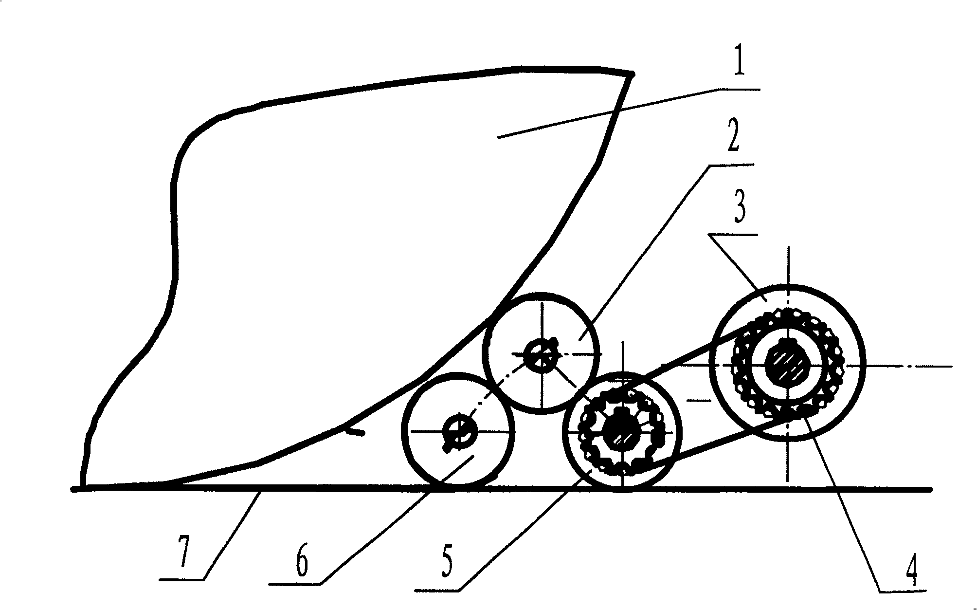
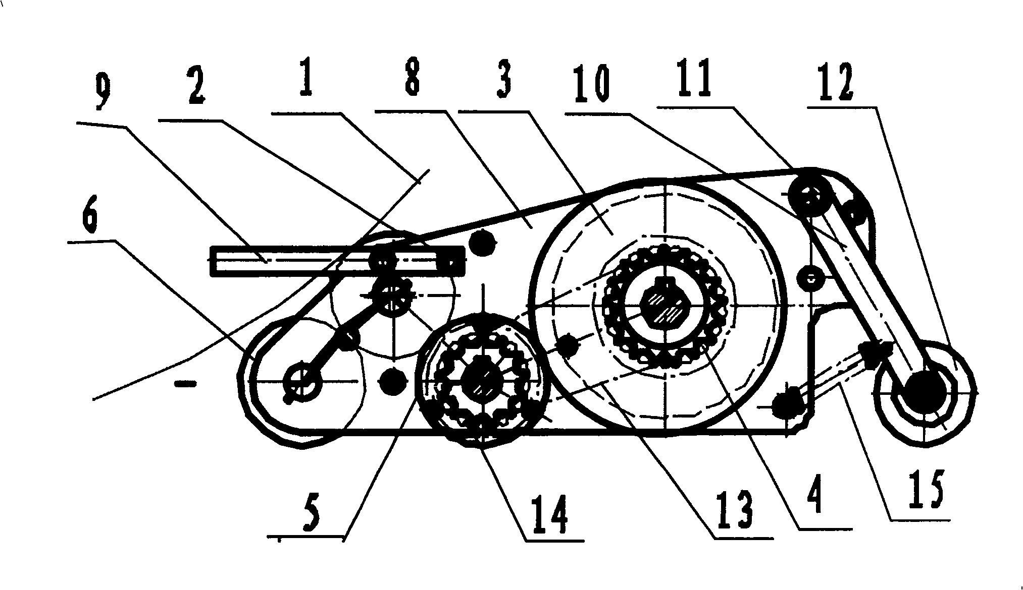
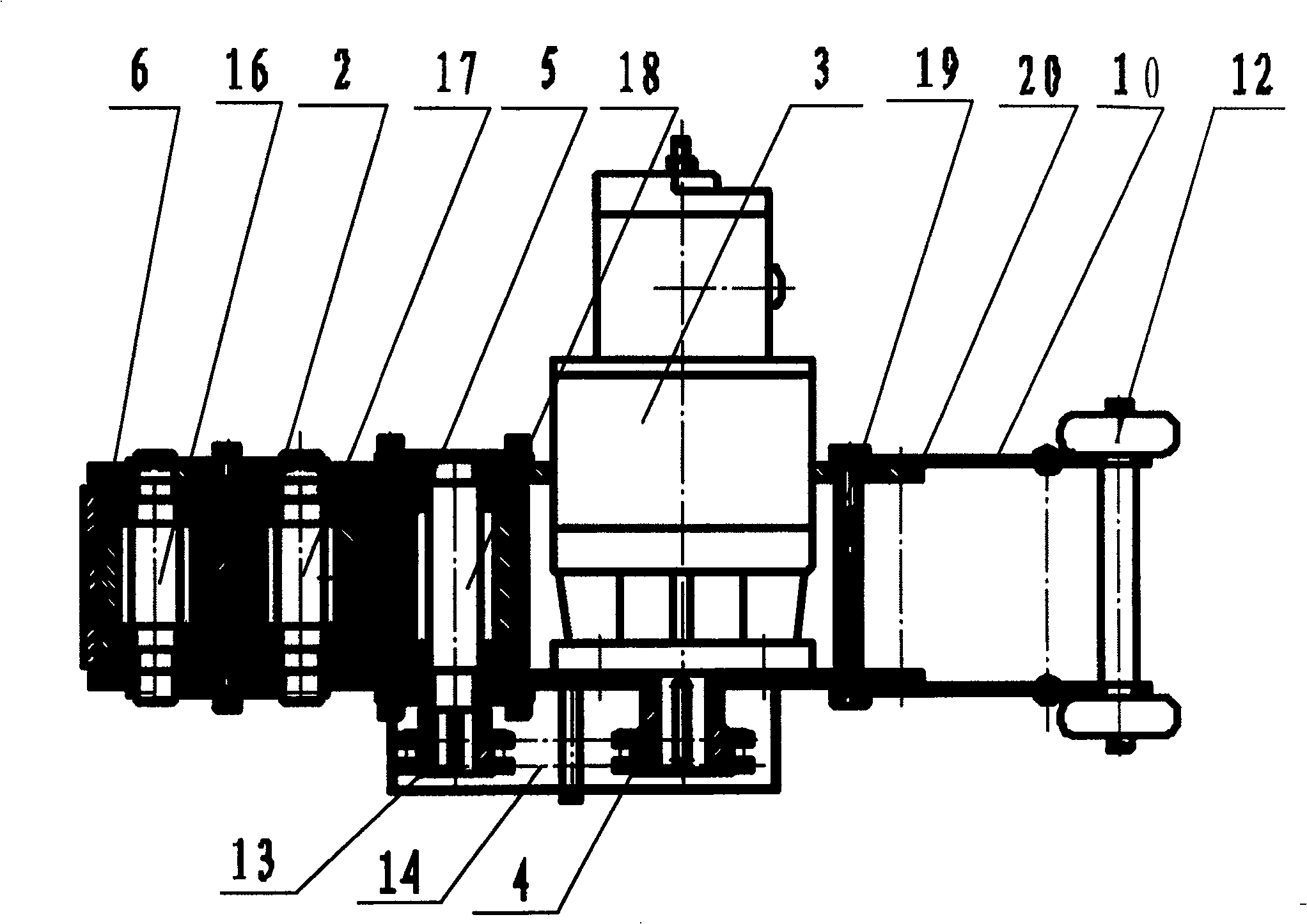
[0019] The accompanying drawings show the structural principle diagram of the present invention and the structural schematic diagram of an embodiment, and the present invention will be further described below in conjunction with the accompanying drawings and the embodiment.

[0020] From attached figure 1 It can be seen from the figure that the present invention belongs to a method and device for pushing a vehicle. The movement of the pushed vehicle is driven by the frictional force of the push wheel 2 and the wheel 1 of the pushed vehicle turning in the opposite direction. It is a wedge-type push cart device installed under the wheel 1 of the pushed vehicle. There is a push wheel 2 on the push cart device. Push the wheel 1 of the pushed vehicle to propel the vehicle.

[0021] The wedge-type trolley device is a three-wheel combination friction wheel train mechanism, wherein one friction wheel is directly attached to the wheel of the driving vehicle as the push wheel 2; one f...


PUM


Abstract

A pneumatic wedge-type method and mechanism for pushing vehicle features that the vehicle is pushed to move by the friction force between the push wheel and the wheel of the vehicle to be pushed. Its advantages are light weight and small size.

Description

technical field [0001] The invention belongs to a method for pushing a cart, in particular to a method for pushing a locomotive, and also relates to a cart device, in particular to a cart device for a locomotive. It is suitable for the manufacture and repair of railway locomotives and vehicles, the repair of automobiles and other vehicles, etc., for the movement of the car body. Background technique [0002] At present, all kinds of vehicle factories, locomotive depots, depots, and even auto repair shops rely on external traction to move when their own power fails (or they do not have power themselves). Most of the current car bodies are moved by shunting. Or the hoist type wire rope traction operation, the personnel that mobile vehicle operation needs like this is many, and operation is complicated, causes short-distance moving cost height, and wire rope traction operation is not very safe again, has many disadvantages. In order to solve the problems referred to above, man...

Claims


Application Information

Patent Timeline
Patent Type & Authority Patents(China)
IPC IPC(8): B61J3/12
Inventor 何晓红刘彦专罗卫伟
Owner 株洲市长征机电设备有限公司
Why Eureka
Try Eureka