
Electrodeless lamp system

A technology of electrodeless lamps and electric power, which is applied to discharge lamps, circuits, electric light sources, etc., and can solve problems such as shortening the service life of magnetrons

Inactive Publication Date: 2008-09-17
ORC MFG
View PDF4 Cites 0 Cited by
  • Summary
  • Abstract
  • Description
  • Claims
  • Application Information

AI Technical Summary

Problems solved by technology

This situation is so stressful on the magnetron that it becomes a huge factor in shortening the lifetime of the magnetron

Method used


Image

  • Electrodeless lamp system
  • Electrodeless lamp system
  • Electrodeless lamp system

Examples


Embodiment Construction

[0033] Embodiments according to the present invention will be described in detail with reference to the drawings.

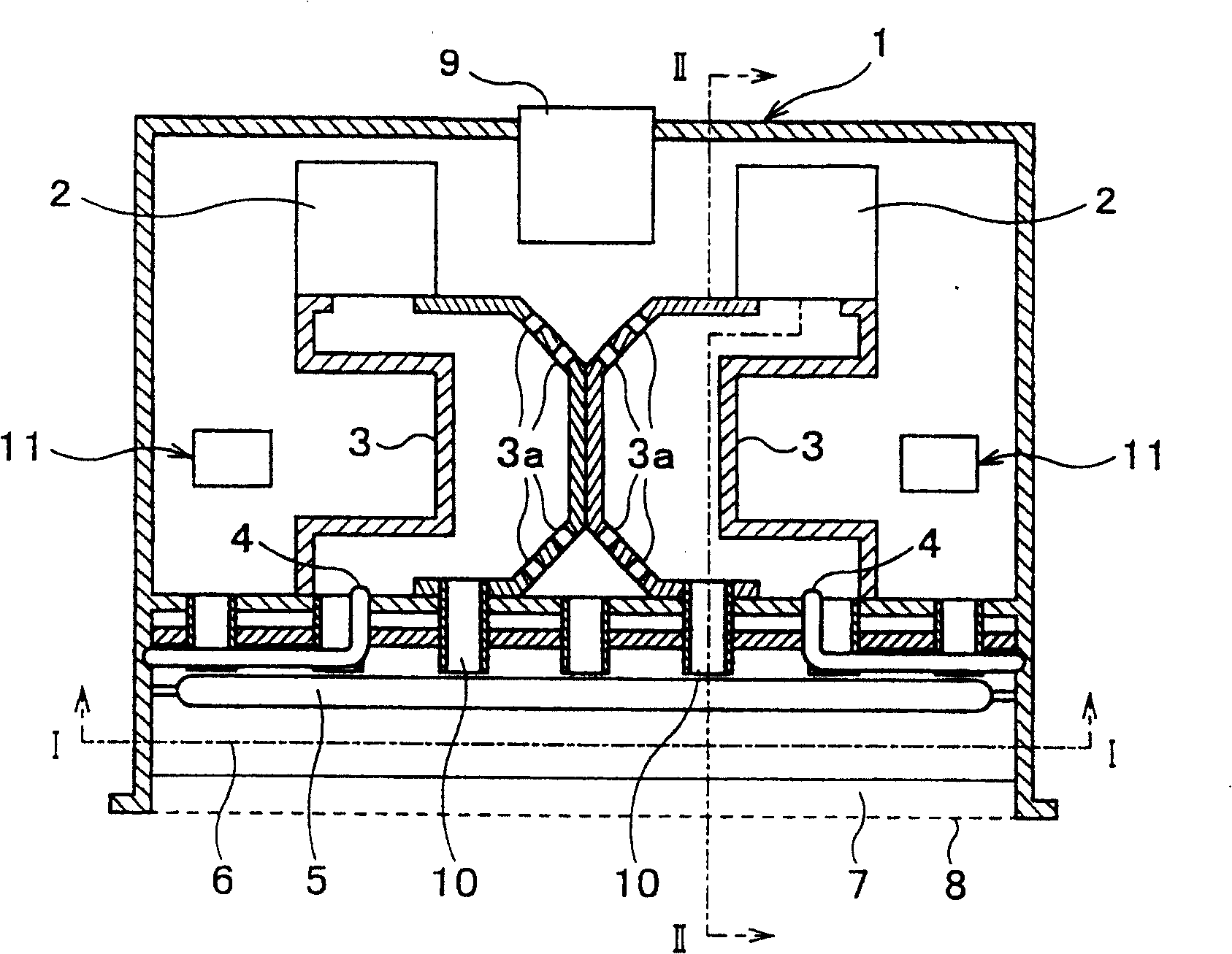
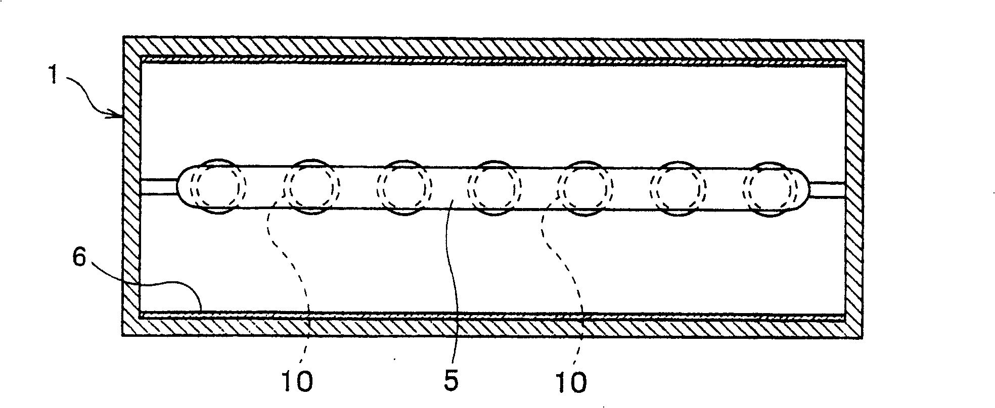
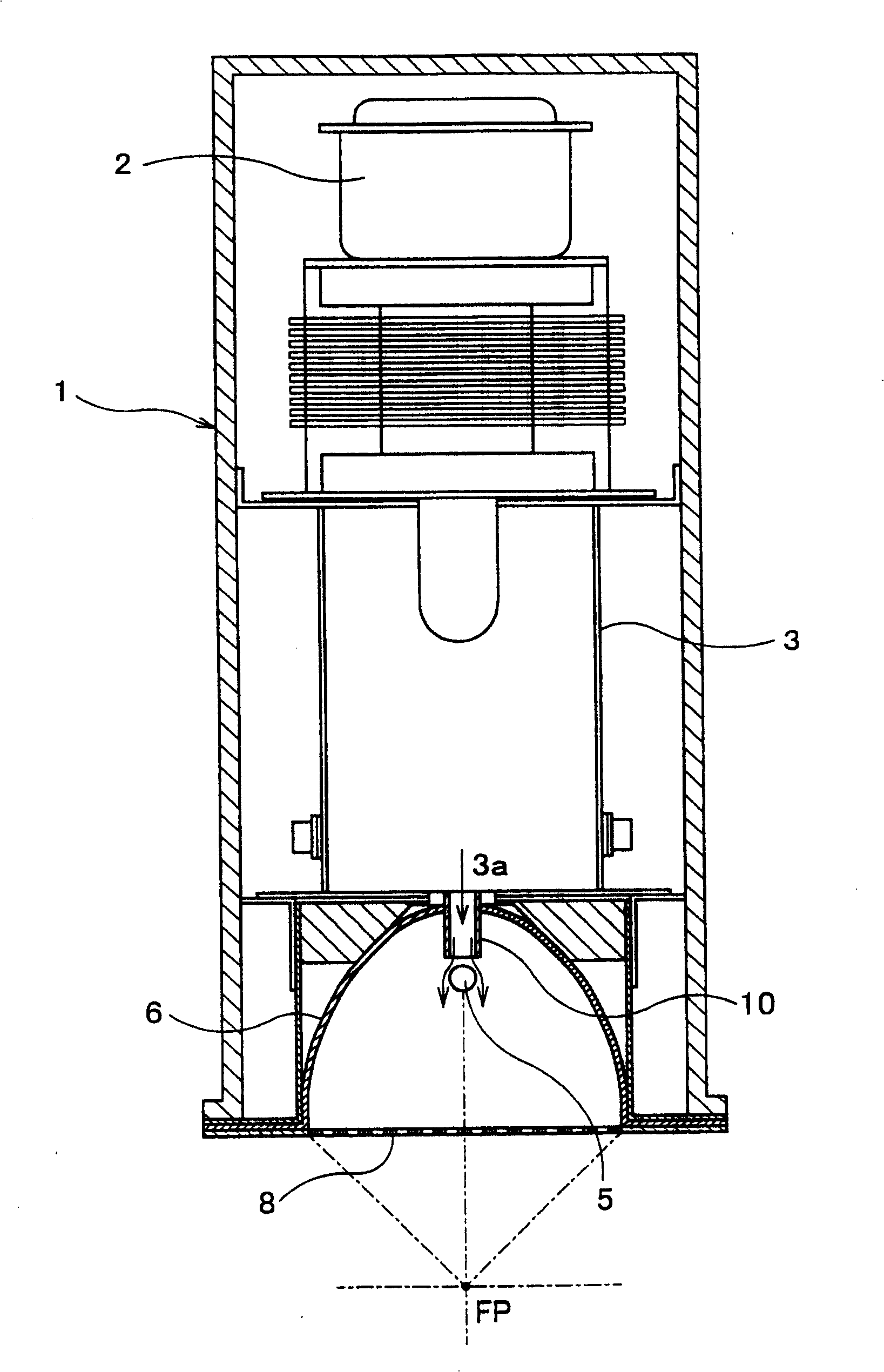
[0034] Figure 1 to Figure 4 One embodiment of an electrodeless lamp system according to the invention is shown. figure 1 is a schematic cross-sectional view of a luminaire using an electrodeless lamp system, figure 2 is a bottom view. image 3 It is a partially enlarged cross-sectional view of the electrodeless lamp. Figure 4 is an explanatory diagram showing a control circuit for driving a magnetron.

[0035] Such as Figure 1 to Figure 3 As shown, the reference numbers 1 to 11 represent the following contents respectively: 1 represents the lamp box. 2 denotes a magnetron generating a microwave electromagnetic field. 3 denotes a waveguide. 4 represents an antenna. 5 represents an electrodeless lamp. 6 represents reflector. 7 denotes a microwave resonator. 8 represents a reflective microwave network. 9 represents a cooling fan. 10 represents the ...


PUM


Abstract

An emission element enclosed inside an electrodeless lamp 5 is excited by an electromagnetic field of a microwave irradiated from a magnetron 2 for emitting a light from the electrodeless lamp 5. A soft-starting method is provided such that an electric power enough to drive the magnetron 2 is gradually increased. The soft-starting method is to prevent the magnetron from being destroyed caused by a self-heating due to a reflected wave of the microwave and is used when a light begins to be emitted from the electrodeless lamp 5. Accordingly, the electrodeless lamp system is provided such that a breakage of the magnetron caused by the self-heating due to the reflected wave of the microwave can be prevented.

Description

technical field [0001] The present invention relates to an electrodeless lamp system for exciting the electrodeless lamp by microwaves to emit light, and more particularly to an improved electrodeless lamp system for outputting high energy light from an electrodeless lamp. Background technique [0002] Electrodeless lamps emit light in such a way that a luminescent element (such as mercury or the like) encapsulated in the lamp is excited by microwaves emitted from a magnetron via an antenna to emit light from the lamp. [0003] For example, it is well known that a microwave oven, which is a common household commodity, heats an object to be heated (such as a frozen food, etc.) to about 600W by using microwaves emitted from a magnetron. Since this microwave output from the magnetron is low-energy, this type of microwave oven will not be damaged by the self-heating of the magnetron. [0004] However, when the microwave power output from the magnetron is high power, for example...

Claims


Application Information

Patent Timeline
Patent Type & Authority Patents(China)
IPC IPC(8): H01J65/04H05B41/24H05B6/68H05H1/46
CPCH01J65/044H05B41/24
Inventor 铃木昭夫多田猛加藤泰成
Owner ORC MFG
Learn More