
High-power millimeter wave matching load

A matching load and millimeter wave technology, applied in the direction of waveguide devices, circuits, electrical components, etc., can solve the problems of increased reflected wave power, increased system, damage, etc., to reduce reflected wave power, reduce ignition probability, and reduce manufacturing cost effect

Active Publication Date: 2021-08-24
INST OF APPLIED ELECTRONICS CHINA ACAD OF ENG PHYSICS
View PDF9 Cites 0 Cited by
  • Summary
  • Abstract
  • Description
  • Claims
  • Application Information

AI Technical Summary

Problems solved by technology

In addition, there are micropores in part of the absorbing layer. Under high power conditions, sparks are prone to occur at the micropores and cause damage to part of the absorbing layer.
In addition, due to the longer output power time, part of the absorbing layer and the absorbing cavity body will be deformed to varying degrees due to different thermal expansion coefficients, causing part of the absorbing layer to fall off from the absorbing cavity body
With the damage and shedding of part of the reflective layer, the working performance of the matching load will also change, resulting in an increase in the reflected wave power and increasing the risk of system damage
[0005] At the same time, if stainless steel water pipes are used to absorb the incident high-power millimeter waves, although various shortcomings caused by coating part of the reflective layer can be avoided, the low absorption rate of stainless steel for millimeter waves will reflect and propagate multiple times in the matching load, which will cause Stronger reflected waves, increasing the risk of system damage

Method used


Image

  • High-power millimeter wave matching load
  • High-power millimeter wave matching load
  • High-power millimeter wave matching load

Examples


Embodiment 1

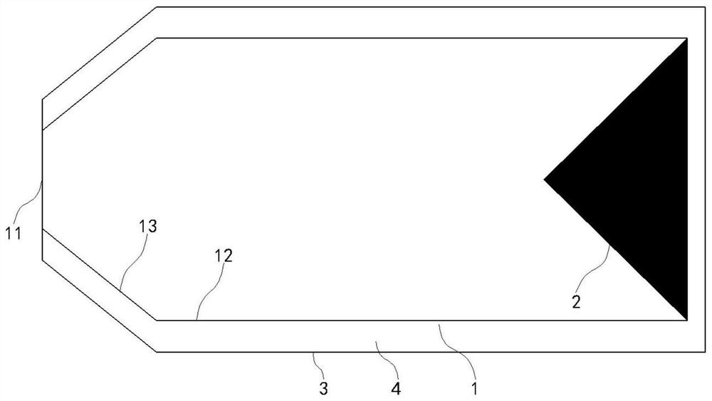
[0048] Such as figure 1 As shown, a high-power millimeter-wave matching load in this embodiment includes a stainless steel load body 1 with a cavity, and the cavity includes a reflection cavity 13 and an absorption cavity 12;

[0049] The beam entrance 11 is set on the load body 1, and the beam enters the cavity through the beam entrance 11;

[0050] The conical mirror 2 is arranged at the other end of the cavity relative to the beam entrance 11, and has a mirror surface facing the inner wall of the absorption cavity 12, so as to reflect the incident microwave beam to the inner wall of the absorption cavity 12;

[0051] The shape of the absorption cavity 12 is cylindrical, and it is located on one side of the reflector 2 for absorbing and reflecting the microwave beam reflected from the reflector 2;

[0052] The reflective cavity 13 is arranged at the front end of the absorbing cavity 12. The reflective cavity 13 is in the shape of a truncated cone and has a reflective cavit...

Embodiment 2

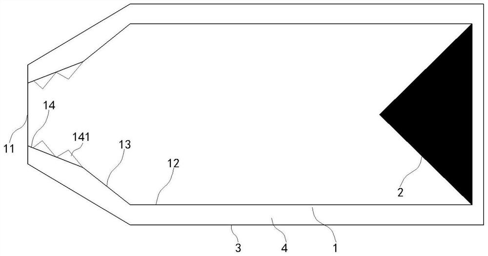
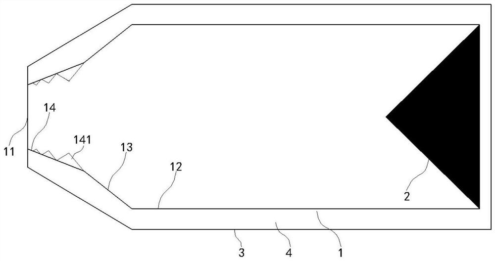
[0056] Such as figure 2 As shown, a high-power millimeter-wave matching load in this embodiment includes a stainless steel load body 1 with a cavity, and the cavity includes a pre-absorption section 14, a reflection cavity 13 and an absorption cavity 12 in turn, and the pre-absorption section 14 setting the toothed structure 141;

[0057] Such as Figure 5 As shown, the pre-absorption section 14 is trumpet-shaped, and the angle α between the pre-absorption section 14 and the horizontal plane is smaller than the angle β between the reflection cavity surface and the horizontal plane;

[0058] The beam entrance 11 is set on the load body 1, and the beam enters the cavity through the beam entrance 11;

[0059] The conical mirror 2 is arranged at the other end of the cavity relative to the beam entrance 11, and has a mirror surface facing the inner wall of the absorption cavity 12, so as to reflect the incident microwave beam to the inner wall of the absorption cavity 12;

[00...


PUM


Abstract

A high-power millimeter wave matching load disclosed by the present invention comprises a stainless steel load body which comprises a cavity, wherein the cavity comprises a reflection cavity and an absorption cavity; a beam inlet which is arranged on the load body, wherein a beam enters the cavity through the beam inlet; a reflecting mirror which is arranged at the other end, opposite to the beam inlet, in the cavity, and is provided with a reflecting mirror surface facing the inner wall of the absorption cavity, wherein the absorption cavity is positioned at one side of the reflecting mirror, and the reflection cavity is arranged at the front end of the absorption cavity, and is provided with a reflection cavity surface facing the absorption cavity; and a shell which is arranged outside the load body, wherein a cooling channel is formed between the shell and the load body. By adopting the high-power millimeter wave matching load, the high-power millimeter wave power can be absorbed, the reflected wave power is reduced, and meanwhile, the manufacturing cost of the matching load is reduced, the ignition probability is reduced, and the service life of the matching load is prolonged.

Description

technical field [0001] The invention relates to a high-power millimeter-wave matching load, belonging to the technical field of matching loads. Background technique [0002] In the experimental research of magnetic confinement thermonuclear fusion, it is necessary to use high-power millimeter waves for electron cyclotron resonance heating. The high-power millimeter-wave source is usually an electric vacuum device (gyrotron). At present, the output power of a single gyrotron has reached the megawatt level, which requires matching loads to achieve high-power millimeter-wave absorption and matching. When outputting high-power millimeter waves, strict requirements are placed on matching loads. Excessive power of reflected waves, poor design or defects can easily cause damage to matching loads, electric vacuum devices, and system shutdown. [0003] At present, the microwave beam is input from the top of the cavity, reflected and diffused by the metal mirror installed at the bott...

Claims


Application Information

Patent Timeline
Patent Type & Authority Applications(China)
IPC IPC(8): H01P1/26
CPCH01P1/264Y02E30/10
Inventor 黄麒力孙迪敏马国武胡林林卓婷婷曾造金马乔生胡芯瑞胡鹏蒋艺
Owner INST OF APPLIED ELECTRONICS CHINA ACAD OF ENG PHYSICS
Learn More