
Vehicle front structure

A technology for the front part of the vehicle body and the vehicle body, which is applied in the directions of the upper structure, vehicle components, and upper structure sub-assemblies, can solve the problems of low collision energy absorption performance, and achieve the effect of improving rigidity and improving absorption performance.

Inactive Publication Date: 2008-10-15
HONDA MOTOR CO LTD
View PDF7 Cites 0 Cited by
  • Summary
  • Abstract
  • Description
  • Claims
  • Application Information

AI Technical Summary

Problems solved by technology

However, in this case, since the upper surface is only a substantially horizontal thin plate, the reaction force against the collision energy from above is extremely small, and thus the collision energy absorption performance is low.

Method used


Image

  • Vehicle front structure
  • Vehicle front structure
  • Vehicle front structure

Examples


Embodiment Construction

[0038] Hereinafter, preferred modes for carrying out the present invention will be described with reference to the drawings. In addition, the "front", "rear", "left", "right", "up", and "down" are consistent with the directions seen by the driver, Fr indicates the front side, Rr indicates the rear side, and L indicates the left side , R represents the right side, and CL represents the vehicle width center (vehicle body center).

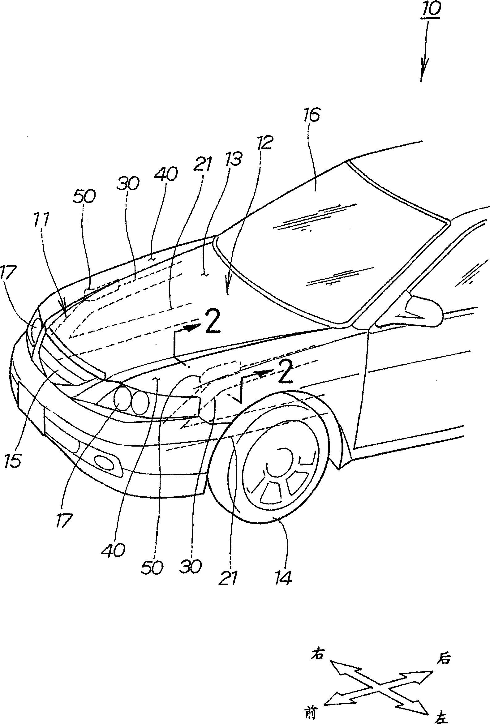
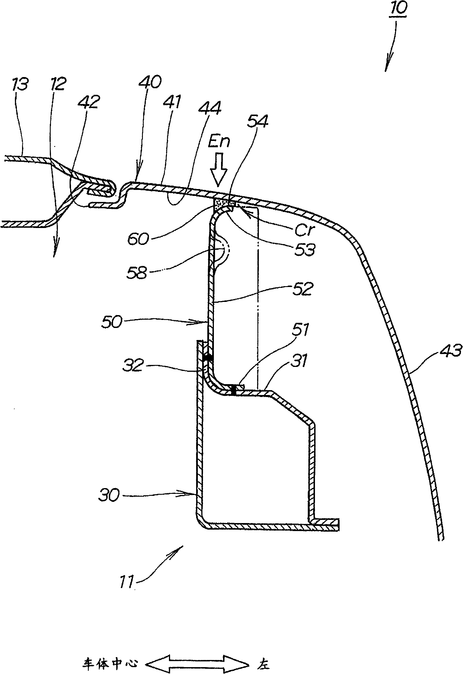
[0039] figure 1 It is a perspective view which shows the structure of the front part of the vehicle of this invention. figure 2 yes figure 1 The sectional view cut along line 2-2 of , which shows the composition of the left side of the front part of the car body.

[0040] Such as figure 1 with figure 2 As shown, the vehicle 10 is an automobile, and the vehicle body 11 (body frame 11) is provided with: a central engine cover 13 that opens and closes the engine compartment 12 at the front of the vehicle body; and left and right front fenders 40, ...


PUM


Abstract

A vehicle front body structure can restrain the weight of the vehicle body and the manufacture cost and can sufficiently absorb the collision energy on a front fender acted from the upward side. The vehicle body (11) is provided with left and right front fenders (40); an upper part covering left and right front wheels on the front part of the vehicle body; left and right upper components (30) extending to the front and the back directions of the vehicle body from the lower side of the left and the right front fenders; left and right fender supporting components (50) of a longitudinal plate shape extending upwards from the upper of the upper component to each lower surface (44) of the left and right front fenders or near the fenders. The left and the right fender supporting components are formed with a bending part and a strip salient (58) extending to the longitudinal length directions of the fender supporting components. Seen from the upward side, the bending part respectively bends on the longitudinal length directions of the left and the right fender supporting components and is crossed with the bending part. A loading agent (60) is arranged between the upper ends (54) of the left and the right front fender supporting components and the lower surfaces of the front and the right front fenders.

Description

technical field [0001] The present invention relates to the structure of the front part of the vehicle body, and in particular to the improvement technique of the periphery of the front fender and the upper member. Background technique [0002] In recent years, the automobile industry has continuously developed such a technology development that when a collision object collides with the front fender of the vehicle, the front fender is deformed to absorb the impact (for example, see Patent Document 1: Japanese Patent Grant Gazette "Patent No. 3052727" ( figure 1 , Figure 17); Patent Document 2: Japanese Patent Grant Gazette "Patent No. 3444773" ( figure 1 ~3)). [0003] The following is based on the attached Figure 7 The vehicle body front structure in the prior art disclosed in Patent Document 1 will be described. Figure 7 It is a schematic diagram of a conventional vehicle body front structure (first prior art). [0004] The front part of the vehicle body in the firs...

Claims


Application Information

Patent Timeline
Patent Type & Authority Patents(China)
IPC IPC(8): B62D25/16B62D25/08
Inventor 柏木正和津岛广通祝迫和彦
Owner HONDA MOTOR CO LTD
Learn More