

Wind direction outlet control unit
A control device and outlet technology, which is applied to the components of pumping devices for elastic fluids, non-variable displacement pumps, machines/engines, etc. Solve problems such as heat dissipation
- Summary
- Abstract
- Description
- Claims
- Application Information
AI Technical Summary
Problems solved by technology
Method used
Image

Examples
Embodiment Construction
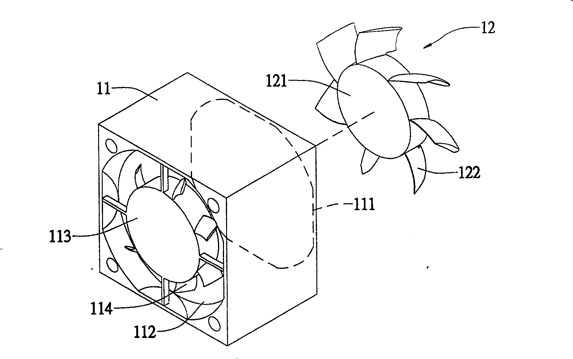
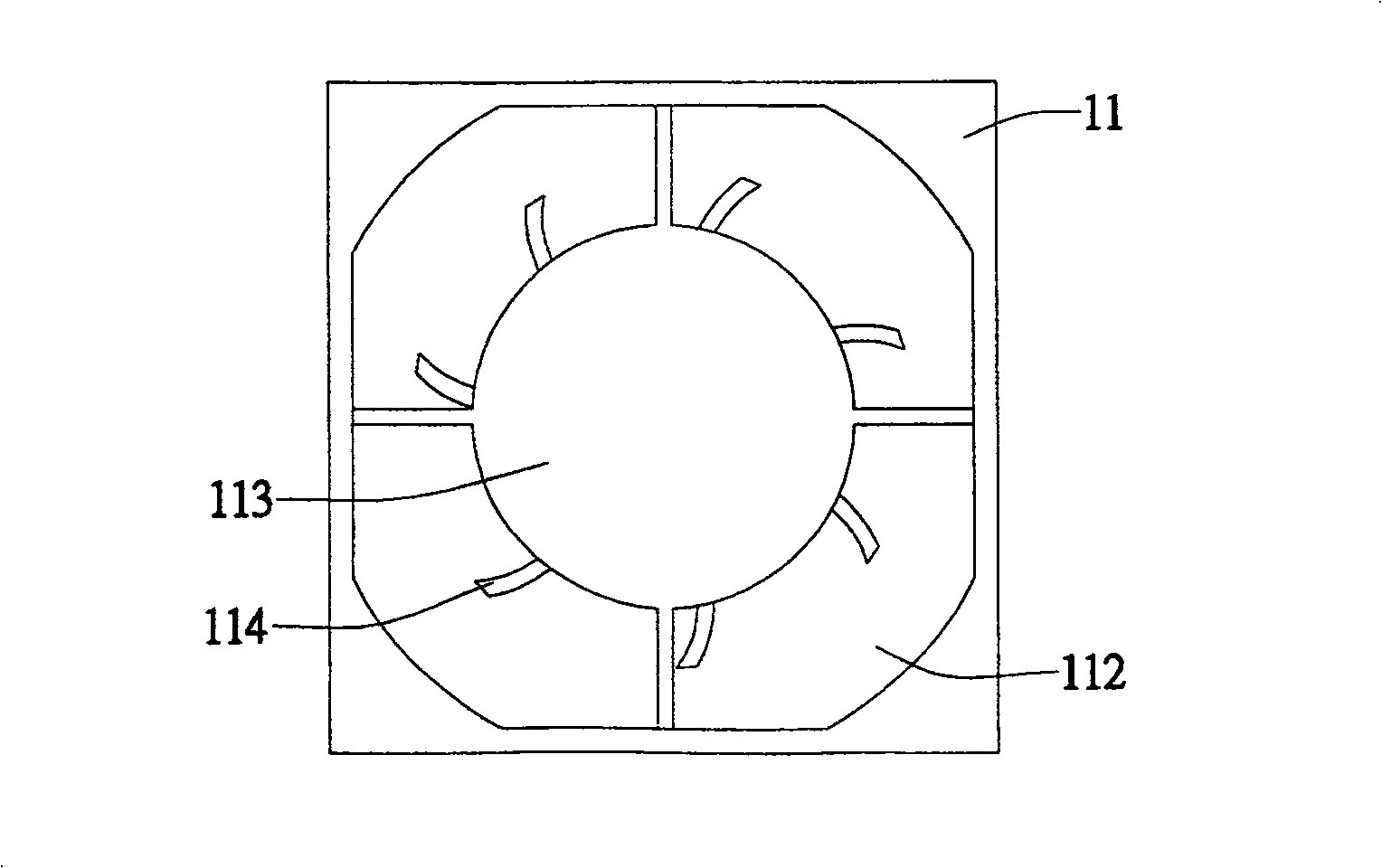
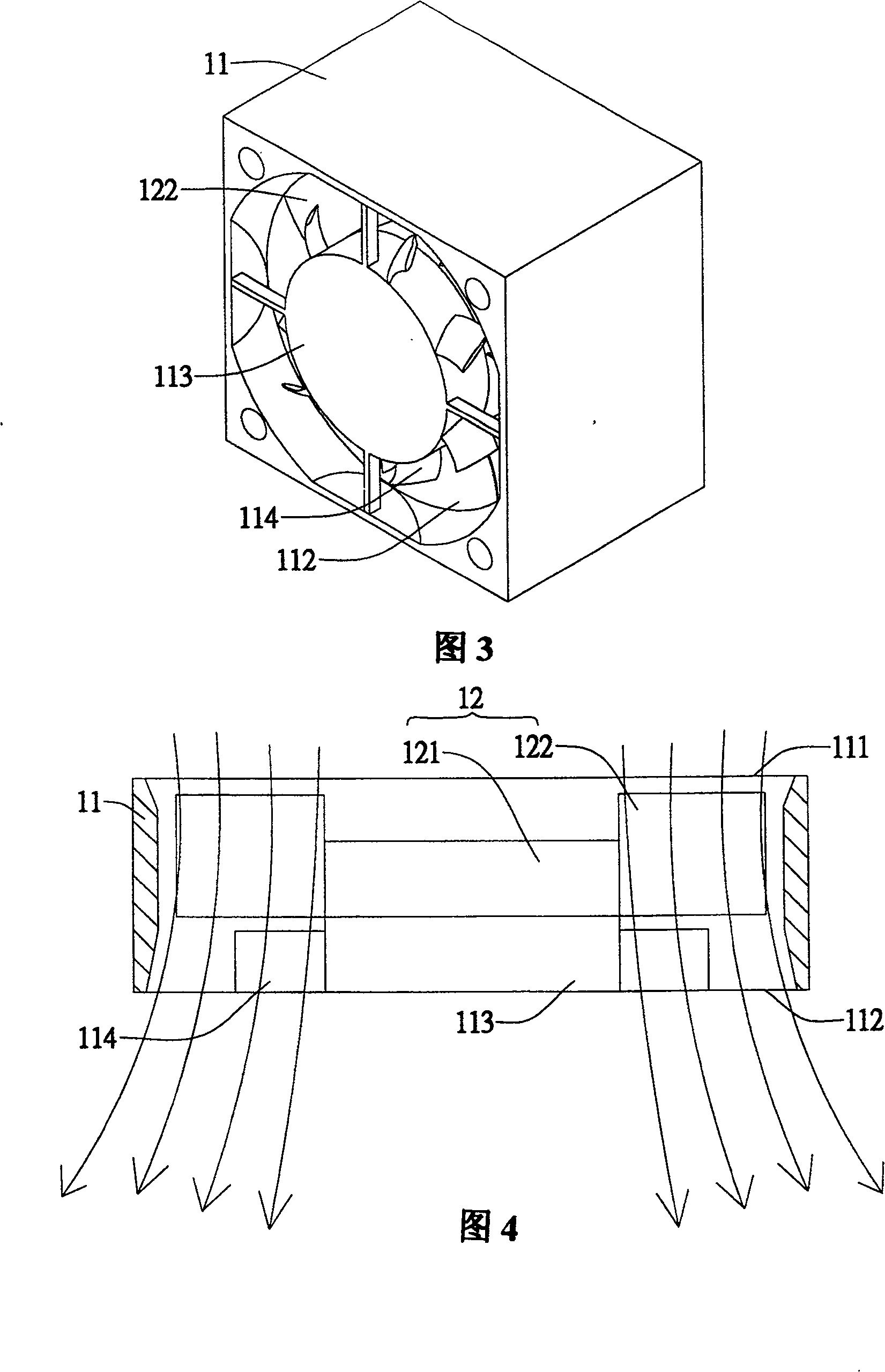
[0081] figure 1 , figure 2 , and Fig. 3 show the first preferred embodiment of the present invention, as shown in the figure, the wind direction outlet control device of the present invention is made up of frame body 11 and fan 12; Wherein this fan 12 is made up of fan hub 121 and fan blade 122 The frame body 11 has an inlet 111 and an outlet 112 for fluid flow, and a hub seat 113 for the fan 12 to be installed is provided in the frame body 11, and a boss is provided on the hub seat 113 at the outlet 112. The radially arranged control vanes 114 are used to change the radial pressure of the fluid flowing in the frame 11, thereby achieving the effect of controlling the direction of the fluid.
[0082] Please refer to FIG. 4 again. When the fan blade 122 rotates, the unsteady flow field changes to drive the fluid to flow in from the inlet 111 and then flow out through the outlet 112. When the fluid flows through the outlet 112, it is controlled by the control blade 114. The in...
PUM
 Abstract
Description
Claims
Application Information