
Fuel injection valve

A fuel injection valve and fuel technology, which can be applied to fuel injection devices, charging systems, machines/engines, etc., can solve the problems of unstable direction or shape of spray foam, hindering the atomization of injected fuel, and increasing fuel pressure loss, etc. Achieve the effects of preventing dripping, promoting separation, and reducing pressure loss

Active Publication Date: 2008-11-12
HITACHI ASTEMO LTD
View PDF8 Cites 0 Cited by
  • Summary
  • Abstract
  • Description
  • Claims
  • Application Information

AI Technical Summary

Problems solved by technology

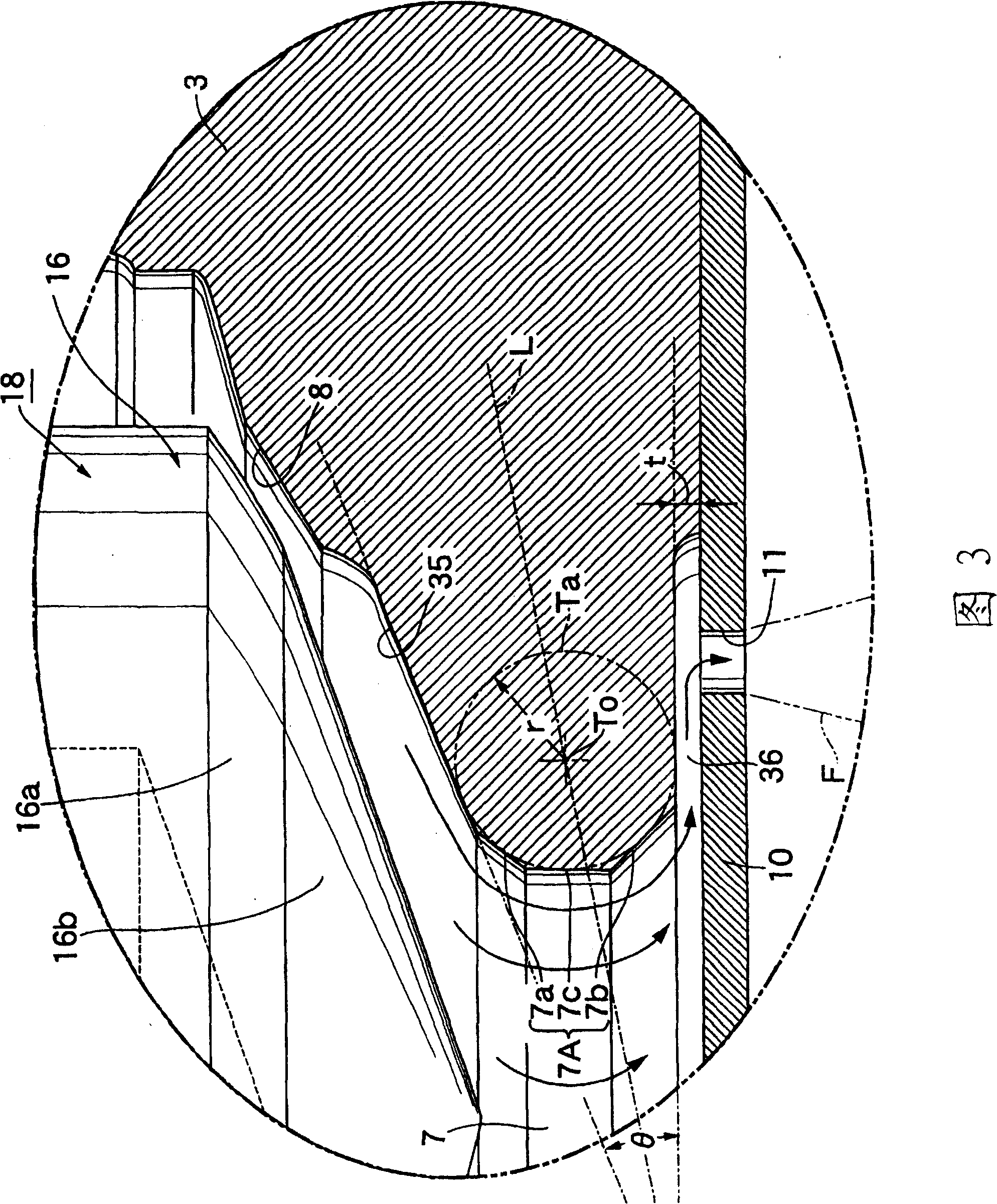
[0005] In addition, in the conventional fuel injection valve, the inner peripheral surface of the outlet hole is cylindrical, and between the bottom surface of the fuel accumulation recess and the inner peripheral surface of the outlet hole, and between the inner peripheral surface of the outlet hole and the fuel diffusion chamber, There is a right angle or close to a right angle between the top surfaces, so when the flow of fuel reverses at the outlet hole, a large number of swirls are generated on the inner side of the reversal, and such swirls increase the pressure loss of the fuel and reduce the injection quantity , or hinder the atomization of the injected fuel from the fuel injection hole, which will cause the direction or shape of the spray foam to become unstable, etc.

Method used


Image

  • Fuel injection valve
  • Fuel injection valve
  • Fuel injection valve

Examples


Embodiment 1

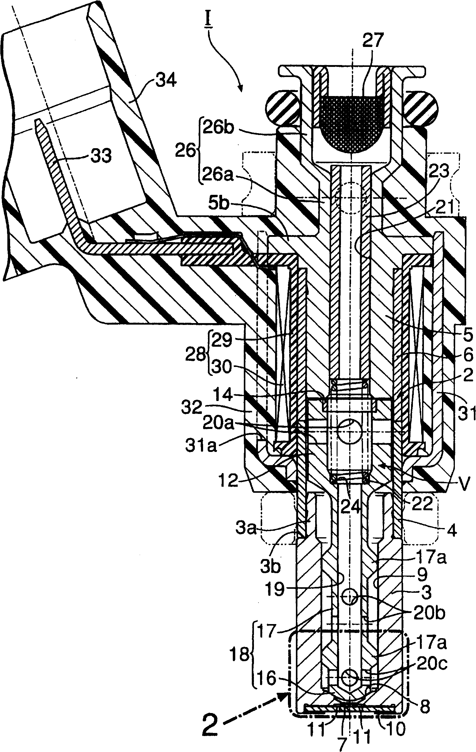
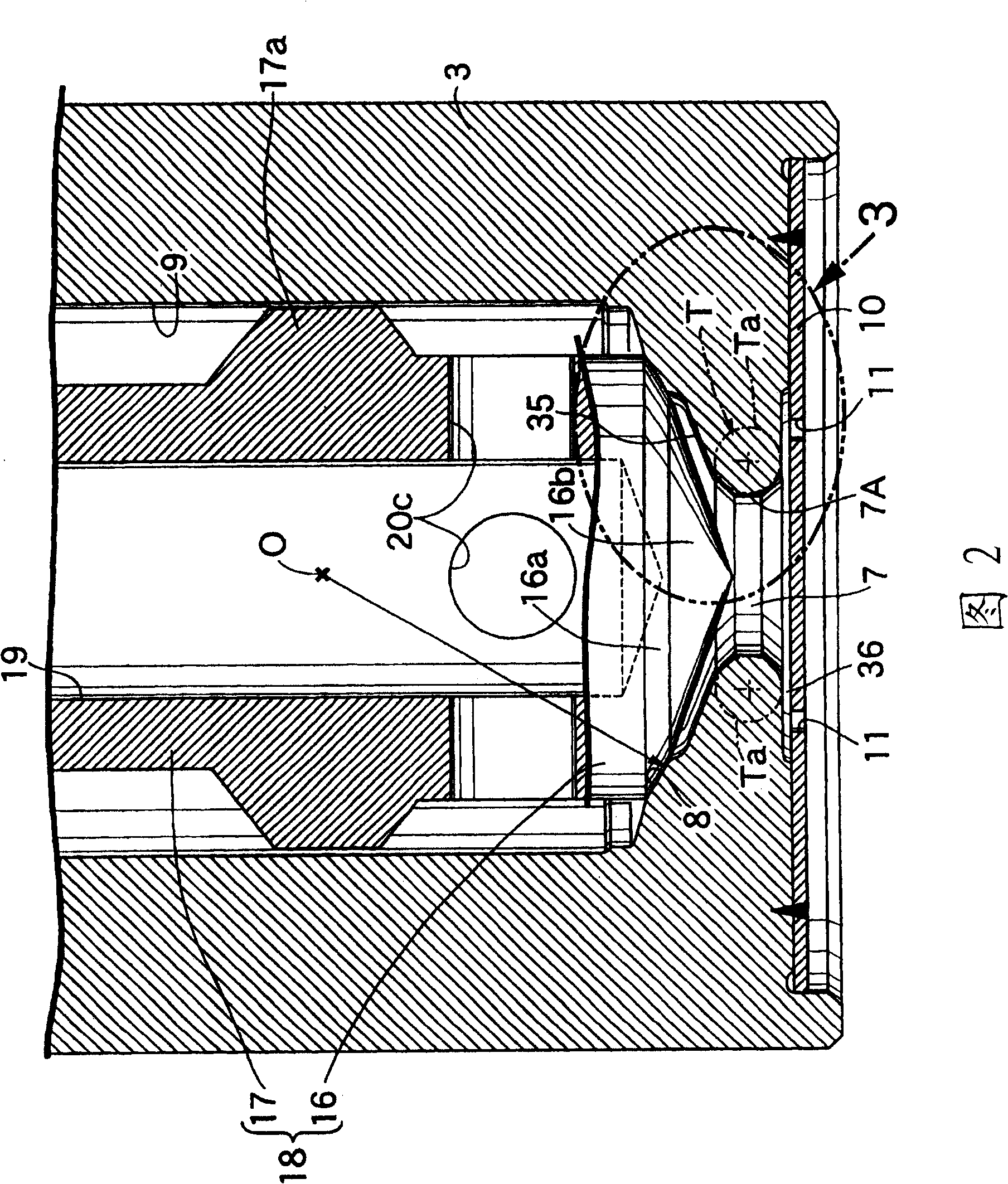
[0022] refer to figure 1 ~ Fig. 3 illustrates the embodiment of the present invention, at first in figure 1 2, the valve housing 2 of the electromagnetic fuel injection valve 1 for an internal combustion engine is made of a cylindrical valve seat member 3, a magnetic cylinder 4 and a non-magnetic cylinder 6, and the valve seat member 3 has a front end. The valve seat 8 ; the magnetic cylinder 4 is coaxially coupled to the rear end of the valve seat member 3 ; the non-magnetic cylinder 6 is coaxially coupled to the rear end of the magnetic cylinder 4 .

[0023] The valve seat member 3 has an annular shoulder 3b from its outer peripheral surface, and has a connecting cylindrical portion 3a at the rear end portion, and the connecting cylindrical portion 3a protrudes toward the magnetic cylinder 4 side. The inner peripheral surface of the front end of the magnetic cylinder 4, and the front end surface of the magnetic cylinder 4 is brought into contact with the annular shoulder 3b...


PUM


Abstract

A fuel injection valve having a funnel-like fuel collection recess (35) provided between a valve seat (8) and exit hole (7) of a valve seat member (3) and collecting fuel having passed the valve seat (8) to guide it to the exit hole (7), and having a flat fuel diffusion chamber (36) provided between opposed surfaces of the valve seat member (3) and an injector plate (10) and diffusing the fuel having passed the exit hole (7) to radially outward to guide it to fuel nozzles (11). The inner peripheral surface (7A) of the exit hole (7) is formed along an inner peripheral side curved surface of an imaginary torus (T) so as to be continuous to the bottom surface of the fuel collection recess (35) and the ceiling surface of the fuel diffusion chamber (36). Vortexes at the exit hole of the valve seat member at the time of inversion of fuel are prevented from occurring, and this reduces pressure loss of the fuel. As a result, reduction of injection fuel is restricted, atomization of the injected fuel is promoted, and the form of a spray of the injected fuel is stabilized.

Description

technical field [0001] The present invention relates to a fuel injection valve mainly used in a fuel supply system of an internal combustion engine, and in particular to an improvement of a fuel injection valve having: a valve seat member having a valve seat at one end and penetrating through the valve seat The outlet hole at the center of the valve body; the valve body, which is accommodated in the valve seat member, and performs opening and closing operations relative to the above-mentioned valve seat; and the injection plate, which is joined to one end surface of the valve seat member, and has a A plurality of fuel injection holes arranged at a distance from the outside in the radial direction is provided with a funnel-shaped fuel collecting recess between the valve seat and the outlet hole, and the fuel collecting recess collects the fuel passing through the valve seat and guides it to the outlet hole, On the other hand, a flat fuel diffusion chamber that diffuses the fuel...

Claims


Application Information

Patent Timeline
Patent Type & Authority Patents(China)
IPC IPC(8): F02M61/18
CPCF02M61/1853
Inventor 赤羽根明
Owner HITACHI ASTEMO LTD
Learn More