
Connector contact terminal

A technology of contact terminals and connectors, applied in the direction of contact parts, etc., can solve the problems of affecting the transmission bandwidth and increasing the impedance of the transmission line, so as to achieve the effect of increasing the transmission bandwidth, reducing the capacitive effect, and improving the transmission quality

Inactive Publication Date: 2008-11-12
DONGGUAN DDCONN ELECTRONICS TECH CO LTD
View PDF3 Cites 1 Cited by
  • Summary
  • Abstract
  • Description
  • Claims
  • Application Information

AI Technical Summary

Problems solved by technology

[0004] From the perspective of the contact surface of the contact terminal, the above-mentioned plugging process can be divided into a sliding contact area and a terminal contact area according to the contact position. Since the final stroke of the butt terminal is to reach the terminal contact area, the sliding contact area immediately becomes the contact terminal and terminal contact area. The overlapping part of the butt joint terminal, in terms of electrical characteristics, this overlapping part will produce a capacitive effect, increase the impedance of the transmission line, and then affect the transmission bandwidth

Method used


Image

  • Connector contact terminal
  • Connector contact terminal
  • Connector contact terminal

Examples


Embodiment Construction

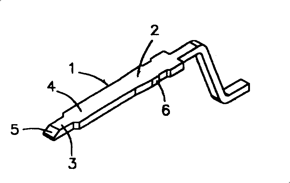
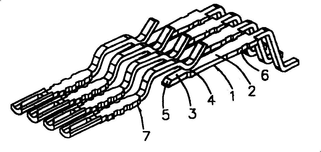
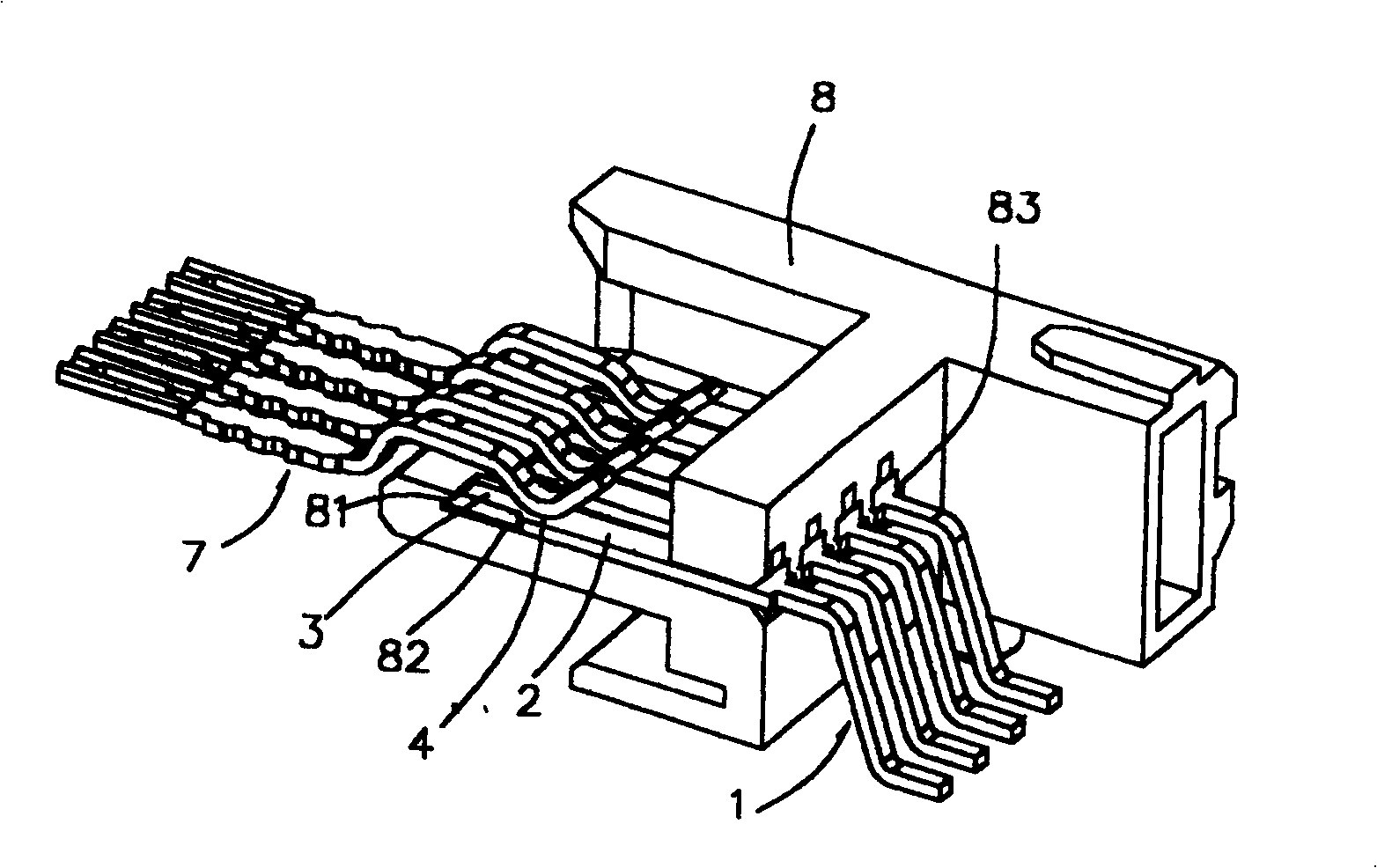
[0016] figure 1 , figure 2 It is a schematic diagram of the structure of the present invention and a schematic diagram of the use of docking, as shown in the figure: the present invention is a contact terminal 1 of a connector, which provides a butt terminal 7 electrically connected along the long axis direction, which has a The narrow and long contact surface 2 with a predetermined width, the two ends of the contact terminal 1 are respectively defined as the butt end and the terminal, along the insertion stroke of the butt terminal (that is, the displacement stroke from the butt end to the terminal direction), this contact surface 2 includes a sliding The contact area 3 and a terminal contact portion 4, the terminal contact position 4 is the predetermined contact position of the butt joint terminal 7, wherein, the surface width of the sliding contact area 3 is smaller than the predetermined width of the contact surface 2, therefore, when the butt joint terminal 7 reaches Wh...


PUM


Abstract

The invention relates to a contact terminal of connector. It provides electrical connection of abutting joint terminal along the long axis direction. It has a narrow contact surface that is preset width and take splicing along the abutting joint terminal. The contact surface has a sliding contact area and a terminal contact section. And the presetting width of the sliding contact area is less that that of the contact surface. So, when the abutting joint terminal arrives at the terminal contact location, the capacity effect would be declined and the transmission quality would improve.

Description

technical field [0001] The present invention relates to a contact terminal of a connector, and in particular to a contact terminal used in a high-frequency transmission connector. Background technique [0002] Generally, the connection method of cables and cables is to achieve electrical conduction through the mutual insertion of a connector and a corresponding butt connector. Among them, the connector and the terminal in the butt connector constitute the electrical contact. , for the convenience of description, the two terminals (connector terminal and docking connector terminal) are referred to as contact terminals and docking terminals hereinafter. [0003] In terms of the current connector insertion technology, when the butt terminal and the contact terminal are plugged, the insertion needs to go through a predetermined stroke. When the butt terminal contacts the contact terminal, it needs to slide through a predetermined distance first, and then the butt terminal reache...

Claims


Application Information

Patent Timeline
Patent Type & Authority Patents(China)
IPC IPC(8): H01R13/02
Inventor 张哲嘉
Owner DONGGUAN DDCONN ELECTRONICS TECH CO LTD
Learn More