Motor driving circuit
A motor drive and motor technology, applied in the field of motor drive circuits, can solve the problems of not being able to effectively reduce the motor drive noise, and not directly controlling the motor output current, so as to achieve the effect of reducing the motor drive noise
- Summary
- Abstract
- Description
- Claims
- Application Information
AI Technical Summary
Problems solved by technology
Method used
Image

Examples
Embodiment 1
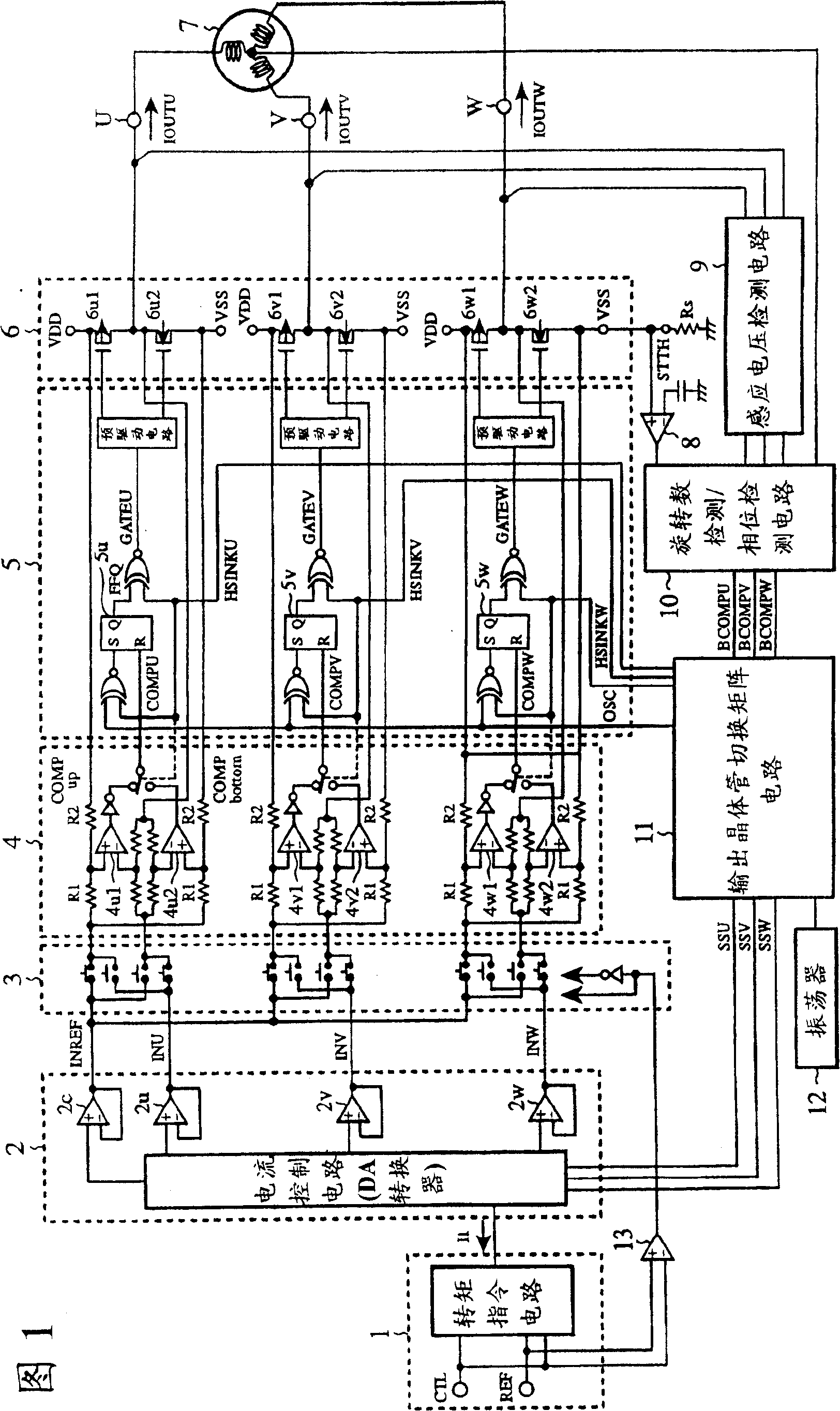
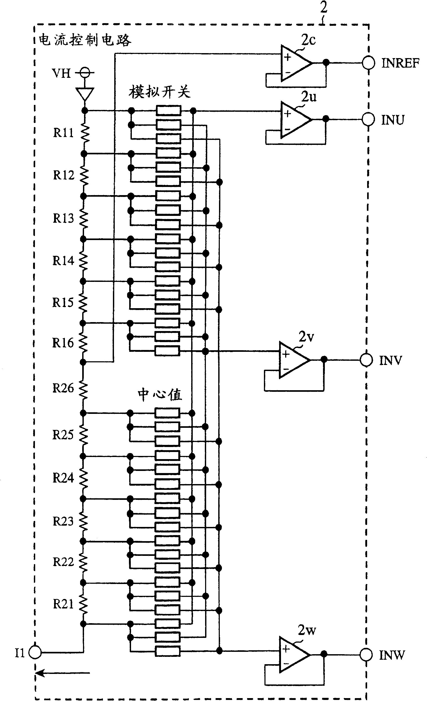
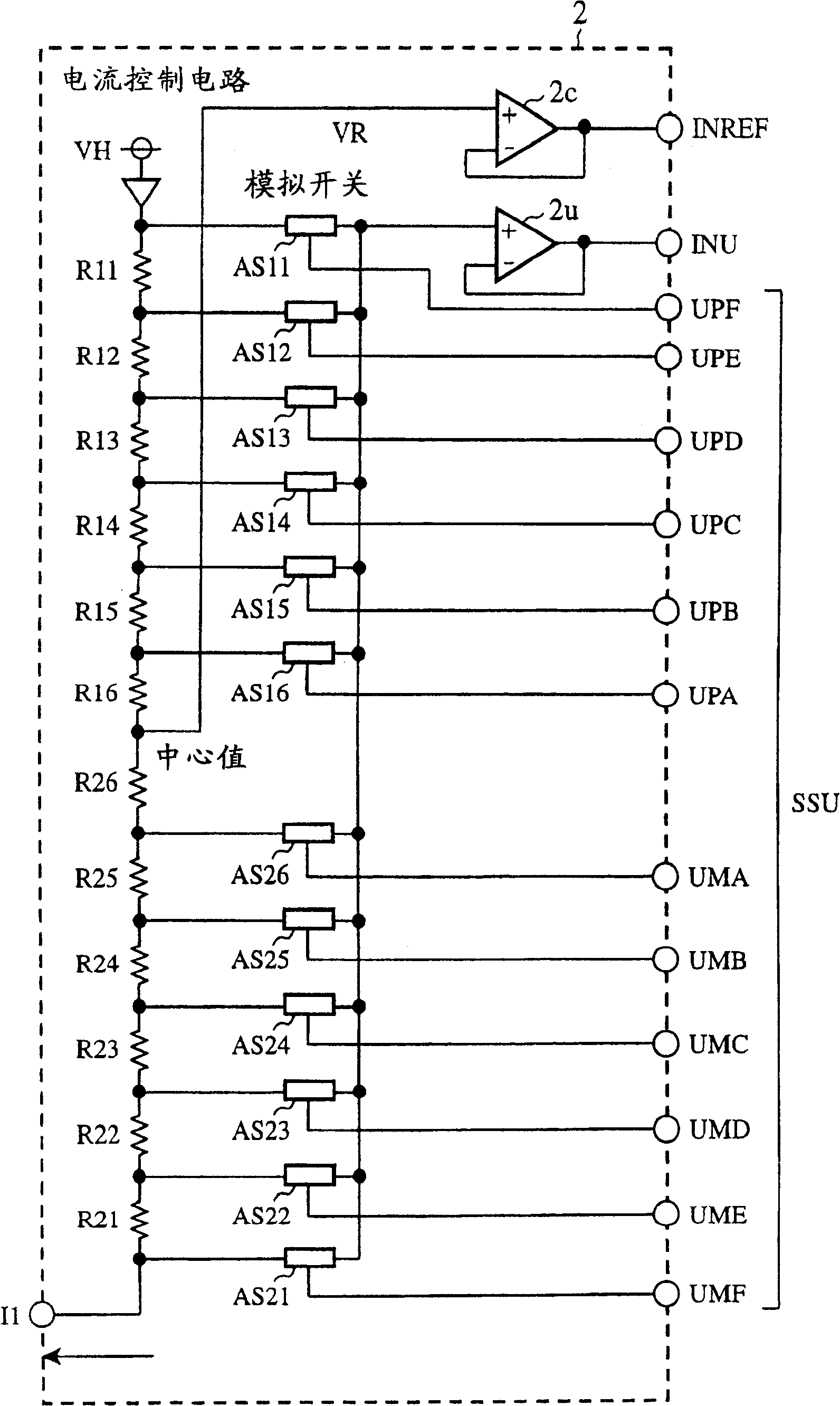
[0033] Fig. 1 is a block diagram showing the structure of a motor drive circuit according to Embodiment 1 of the present invention. figure 2 is a circuit diagram showing the configuration of the current control circuit of the first embodiment. image 3 It is a circuit diagram showing the configuration of a U-phase output current generating section used in the current control circuit of the first embodiment. The torque command circuit 1 (current control means) controls the current control circuit 2 (current control means) using the torque signal I1. For example, the current control circuit 2 composed of a DA converter generates a reference value INREF for generation and control of the three-phase output currents IOUTU, IOUTV, and IOUTW for driving the motor 7, and current control command values INU, INV, and INW (current control command signal).
[0034] The torque direction switching circuit 3, according to the torque command signal output from the torque command circuit 1...
Embodiment 2
[0074] Fig. 10 is a block diagram showing the structure of a motor drive circuit according to Embodiment 2 of the present invention. Components that are the same as or correspond to those shown in FIG. 1 are denoted by the same symbols, and description thereof will be omitted. The motor drive circuit shown in FIG. 10 further includes resistors R30u, R30v, and R30w for detecting output currents IOUTU, IOUTV, and IOUTW of U, V, and W phases, respectively, on the circuit shown in FIG. 1 .
[0075] Resistor R30u is inserted into the connecting part of the first output transistor 6u1 and the second output transistor 6u2, that is, between the output part of the output current IOUTU and the terminal U of the motor 7, and the voltage across the resistor R30u is connected so as to pass through the current detection circuit 4 resistors R1, R2 and comparators 4u1, 4u2 detection. The resistor R30v is inserted between the output portion of the output current IOUTV connected to the first o...
Embodiment 3
[0082] Fig. 11 is a block diagram showing the structure of a motor drive circuit according to Embodiment 3 of the present invention. Components that are the same as or corresponding to those in the motor drive circuit shown in FIG. 1 are denoted by the same reference numerals, and description thereof will be omitted. The motor drive circuit shown in FIG. 11 is equipped with a position detection circuit 20 (position detection unit) instead of the induced voltage detection circuit 9 and the starting current detection circuit 8 shown in FIG. unit). The position detection circuit 20 detects the rotor position of the motor 7 based on the voltage waveform output from the Hall element 21 . The detection result is output from the position detection circuit 20 and input to the rotation speed detection / phase detection circuit 10, and based on the detection result, a zero-crossing signal BCOMP is generated.
[0083] Next, the operation will be described.
[0084] Fig. 12 is a timing c...
PUM
 Abstract
Description
Claims
Application Information
 - R&D
- Intellectual Property
- Life Sciences
- Materials
- Tech Scout
- Unparalleled Data Quality
- Higher Quality Content
- 60% Fewer Hallucinations
Browse by: Latest US Patents, China's latest patents, Technical Efficacy Thesaurus, Application Domain, Technology Topic, Popular Technical Reports.
© 2025 PatSnap. All rights reserved.Legal|Privacy policy|Modern Slavery Act Transparency Statement|Sitemap|About US| Contact US: help@patsnap.com