
Heat radiation structure of microwave oven

A heat dissipation structure and technology for microwave ovens, applied in the field of microwave ovens, can solve the problems of air flow turning, high unit price, no noise, etc., and achieve the effects of reducing driving noise and vibration noise, reducing noise, and improving heat dissipation effect.

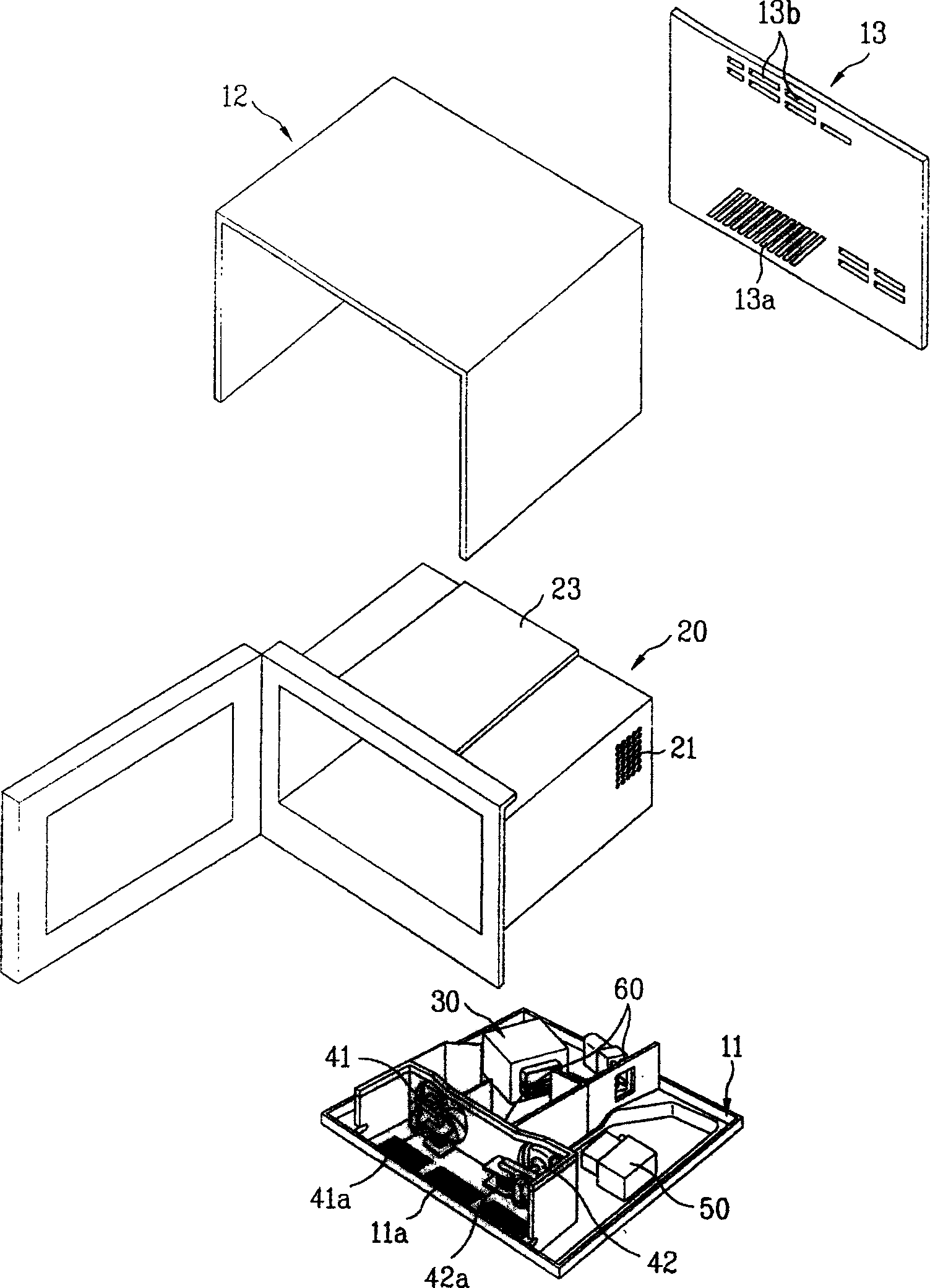
Inactive Publication Date: 2006-01-04
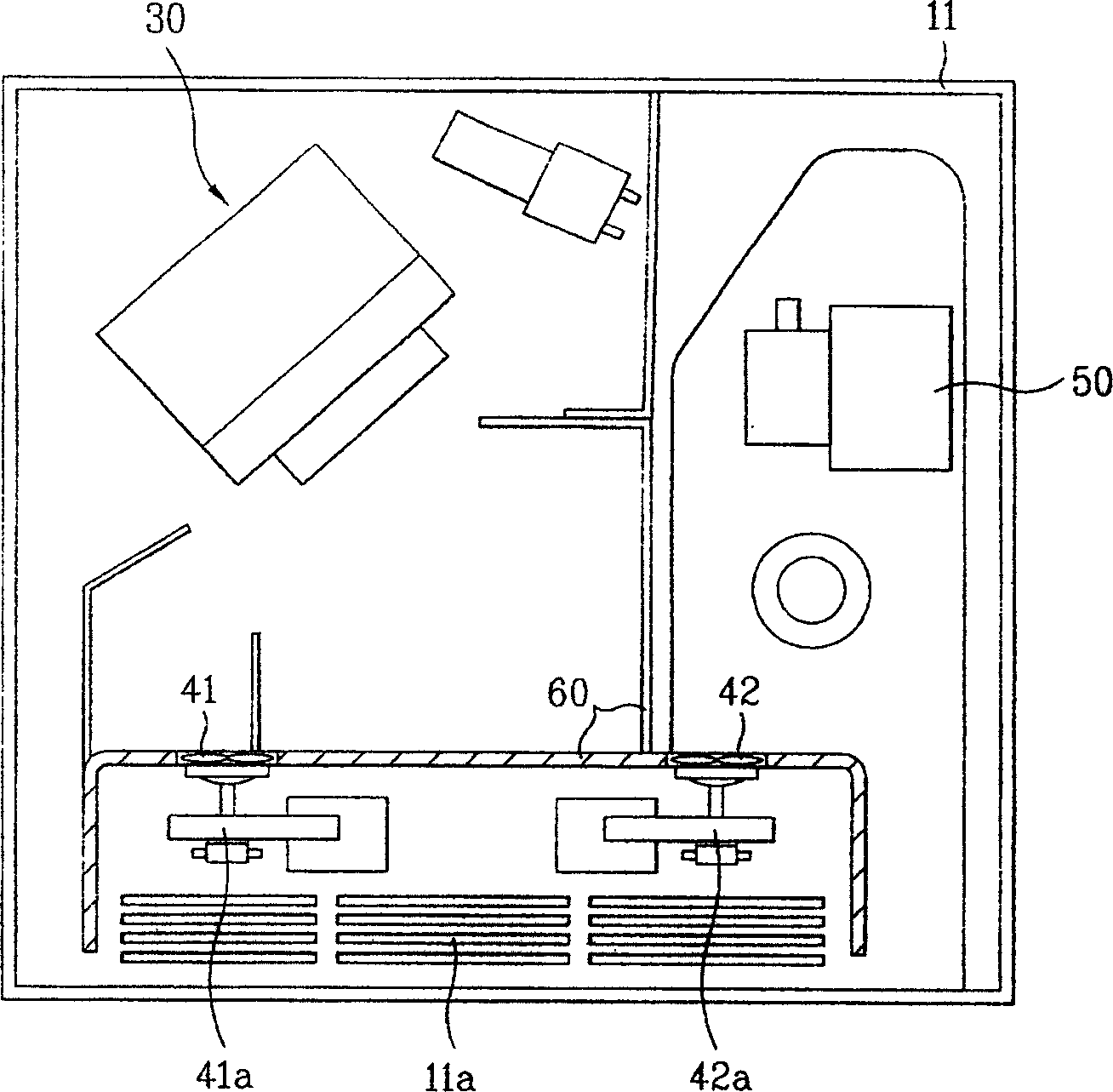
LG ELECTRONICS (TIANJIN) APPLIANCES CO LTD
View PDF0 Cites 0 Cited by
  • Summary
  • Abstract
  • Description
  • Claims
  • Application Information

AI Technical Summary

Problems solved by technology

[0024] In addition, considering that the unit price of the inverter 70 is very expensive and will hardly be used, in the state where the inverter 70 is not used, it is necessary to utilize the position vacated by the inverter 70
[0025] At the same time, in the structure of the prior art, the air flow has a sharp turn, which leads to the generation of more noise, and there is no corresponding structure that can effectively block the noise.

Method used


Image

  • Heat radiation structure of microwave oven
  • Heat radiation structure of microwave oven
  • Heat radiation structure of microwave oven

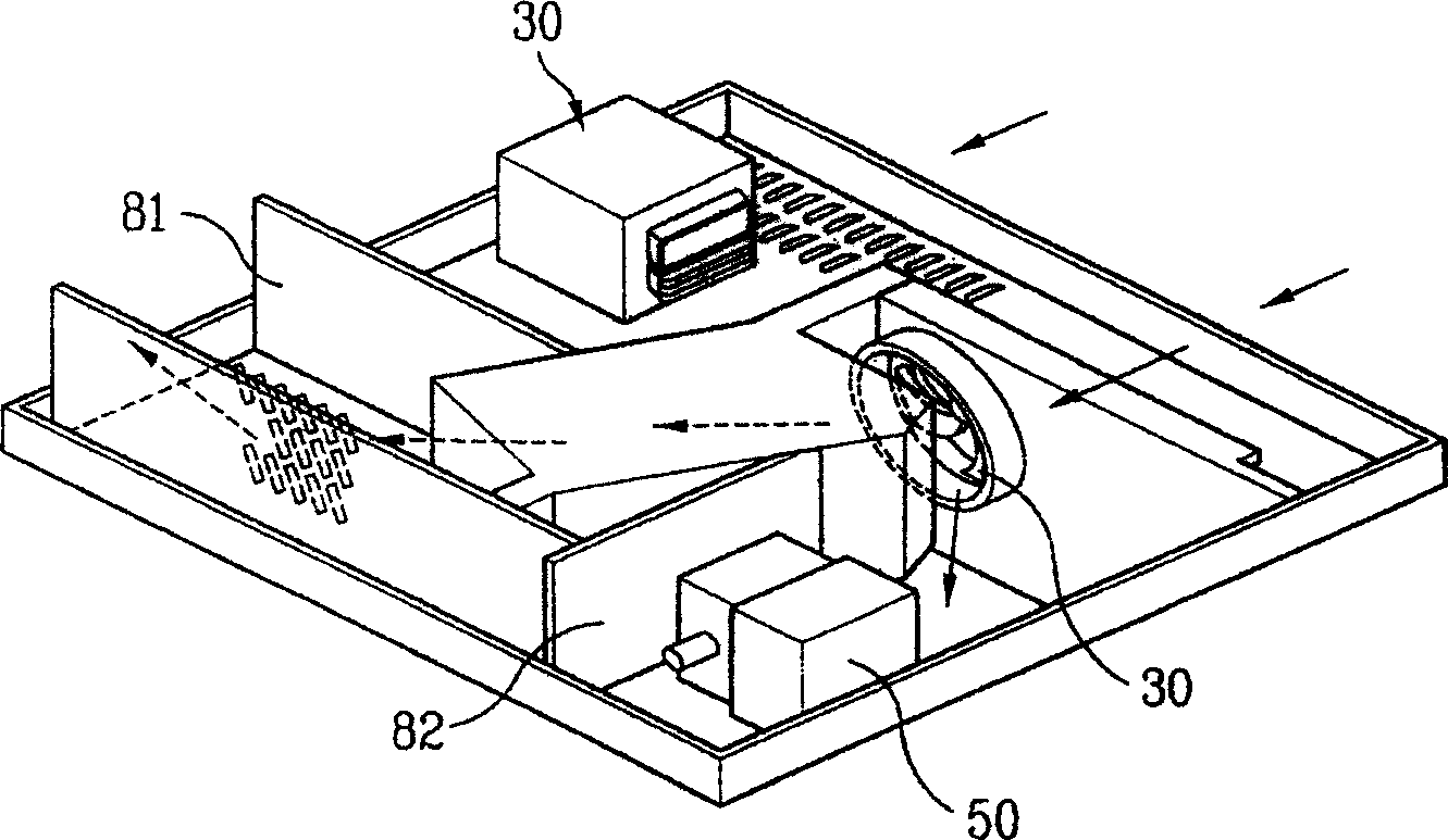
Examples


Embodiment Construction

[0058] Below in conjunction with accompanying drawing and specific embodiment the present invention is described in further detail: Figure 5 A schematic exploded perspective view showing the structure of a microwave oven in an embodiment of the present invention. Image 6 A plan view showing the internal structure of a microwave oven in an embodiment of the present invention.

[0059] First, if Figure 5 and Image 6 As shown, the microwave oven in the embodiment of the present invention generally includes a body, a cabinet 200, an air guiding device 300, a high-voltage transformer 410, a magnetron 420, and an air supply device.

[0060] At the same time, a plurality of air inlets 111 , 131 and air outlets 121 , 132 , 133 are respectively formed on the fuselage.

[0061] Wherein, the air inlets 111, 131 communicate with the rear side space in the lower space inside the fuselage; the air outlets 121, 132, 133 communicate with the front side space in the lower space inside t...


PUM


Abstract

The heat radiation structure of microwave oven includes one oven body with air sucking ports and air exhaust ports and comprising bottom plate, casing and back panel; one oven case inside the oven body to form the cooking chamber; one magnetron on the bottom plate; one air channel in the bottom inside the oven case to lead airflow; one high voltage transformer set inside the air channel; and one air blower to suck air and blow air to the magnetron space. By means of the cooling fan and the fan motor, the present invention can cool the high voltage transformer and the magnetron fluently.

Description

technical field [0001] The invention relates to the field of microwave ovens. Background technique [0002] Generally speaking, microwave ovens use high frequency (about 2450MHz per second) as a heating source, and cook food by disturbing the molecular arrangement in food and using the generated intermolecular frictional heat. [0003] A microwave oven usually consists of a body comprising a bottom plate 11, an appearance frame 12 and a rear panel 13; a cabinet 20 forming a cooking chamber; [0004] figure 1 It is a schematic exploded perspective view showing the internal structure of a conventional microwave oven in which the electric appliance compartment is located at the bottom. figure 2 It shows the plan view of the space structure of the lower body of the microwave oven in the prior art. [0005] figure 1 and figure 2 An example in which the electric appliance compartment is provided at the lower portion of the cabinet 20 is schematically shown in the convention...

Claims


Application Information

Patent Timeline
Patent Type & Authority Applications(China)
IPC IPC(8): F24C7/02
Inventor 朴龙浩
Owner LG ELECTRONICS (TIANJIN) APPLIANCES CO LTD
Learn More