General electric control mechanical gripper with long service life and judgment method for article clamping of general electric control mechanical gripper

A technology of mechanical claw and longevity, applied in the field of mechanical claw, can solve the problems of easy failure, short service life, unable to clamp items, etc., to achieve the effects of high safety and reliability, increased service life, and smooth opening and closing

Pending Publication Date: 2022-03-25
ONCE TOP MOTOR MFG
View PDF0 Cites 0 Cited by
  • Summary
  • Abstract
  • Description
  • Claims
  • Application Information

AI Technical Summary

Problems solved by technology

[0004] Most of the existing mechanical claws on the market are special mechanical claws. According to the different shapes and sizes of parts and objects that need to be grasped, the special mechanical claws are designed with complex structures and complicated driving methods, which are prone to failure and have a short service life. ; In addition, it can only be used for grasping a fixed part or item in general, and cannot be used universally
[0005] In addition, when the current jaws pick up objects, they only rely on human experience to judge whether they can hold objects without destroying them. There is no quantitative basis for judgment, and human subjective judgments are not necessarily accurate, with large errors and easy The item cannot be clamped or the item is damaged due to excessive clamping force

Method used


Image

  • General electric control mechanical gripper with long service life and judgment method for article clamping of general electric control mechanical gripper
  • General electric control mechanical gripper with long service life and judgment method for article clamping of general electric control mechanical gripper
  • General electric control mechanical gripper with long service life and judgment method for article clamping of general electric control mechanical gripper

Examples


Embodiment Construction

[0039] In order to make the object, technical solution and advantages of the present invention clearer, the present invention will be further described in detail below in conjunction with the accompanying drawings and embodiments. It should be understood that the specific embodiments described here are only used to explain the present invention, not to limit the present invention. In addition, the technical features involved in the various embodiments of the present invention described below can be combined with each other as long as they do not constitute a conflict with each other.

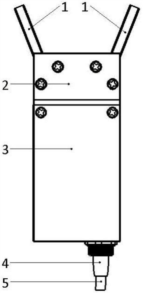
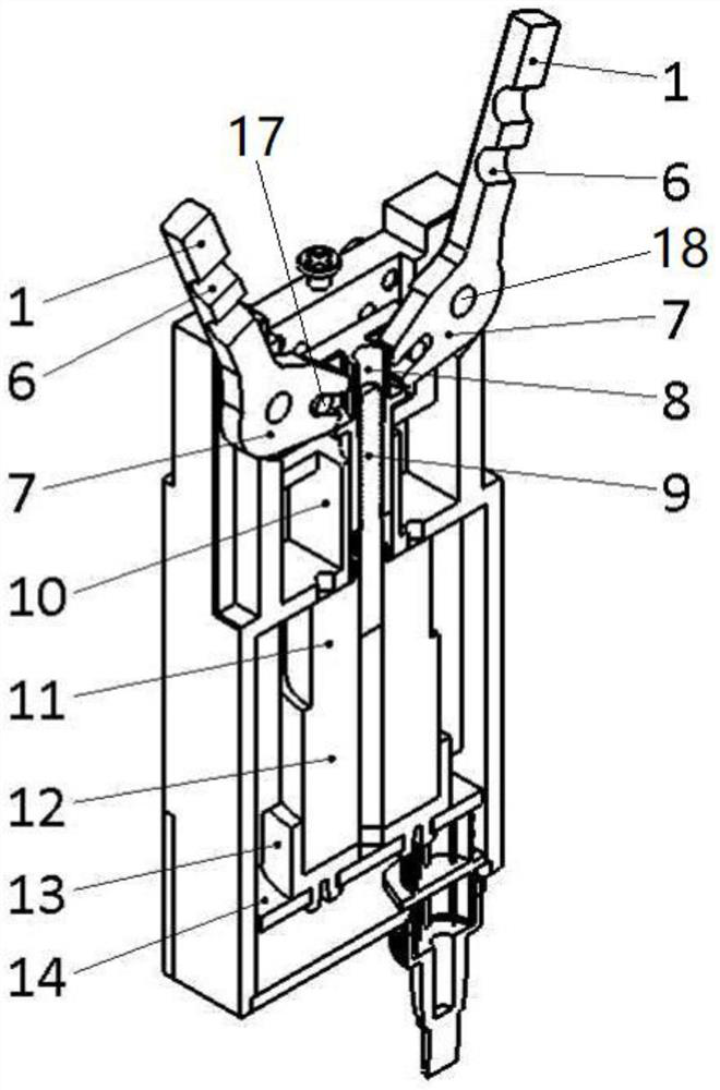
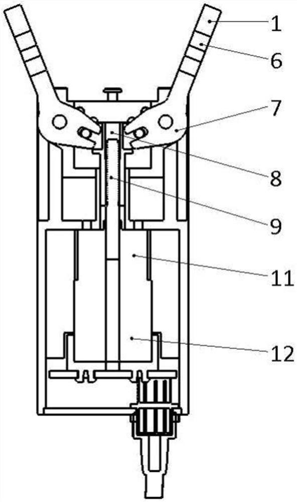
[0040] refer to Figure 1 to Figure 6 , a high-life universal electronically controlled mechanical claw, including a casing, a geared motor, a screw pair, a motor drive board 14, a signal line 5 and two claws, wherein:

[0041] The geared motor and the driving board are all located in the casing and are mounted on the casing, the motor driving board 14 is connected to the geared motor, and one ...


PUM


Abstract

The invention discloses a universal electric control mechanical gripper with long service life. The universal electric control mechanical gripper comprises a machine shell, a gear motor, a lead screw pair, a motor driving plate, a signal line and two clamping jaws. The lead screw pair comprises a lead screw and a lead screw nut, the lead screw is coaxially connected with an output shaft of the gear motor, the lead screw nut comprises a nut body and two connecting parts, each connecting part is provided with a round pin shaft, and each round pin shaft is connected with one clamping jaw. Each clamping jaw comprises a U-shaped connecting rod and a knuckle, the U-shaped connecting rod is fixedly connected with the lower end of the knuckle, an opening of the U-shaped connecting rod is forked into the round pin shaft, so that the U-shaped connecting rod is driven by the round pin shaft to move and rotate relative to the round pin shaft, the upper end of the U-shaped connecting rod is rotatably installed on the machine shell through a hinge shaft, and the lower end of the U-shaped connecting rod is fixedly connected with the knuckle. And the hinged shaft and the round pin shaft are parallel to each other. The mechanical gripper is high in transmission precision and long in service life, opening and closing of the mechanical gripper are smooth, and the service life of the overall structure of the mechanical gripper is prolonged.

Description

technical field [0001] The invention belongs to the field of mechanical grippers, and more specifically relates to a universal electronically controlled mechanical gripper and a method for judging the gripping objects thereof. Background technique [0002] As we all know, robotic equipment is playing more and more roles in helping human beings to produce and live. With the development of science and technology, there are more and more types of robots and industries used in them. In machinery manufacturing, metallurgy, electronics, light industry, etc. In many industries, robots have been used to replace human heavy labor. [0003] As an indispensable part of the robot manipulator, the mechanical claw is often used to grip and carry objects. It has the advantages of convenient use, simple structure and good adaptability. [0004] Most of the existing mechanical claws on the market are special mechanical claws. According to the different shapes and sizes of parts and objects ...

Claims


Application Information

Patent Timeline
IPC IPC(8): B25J9/16B25J15/08B25J15/02
CPCB25J15/08B25J9/16B25J15/0206
Inventor 张松张贝妮周志鹏张子茂
Owner ONCE TOP MOTOR MFG
Why Eureka
Try Eureka