Linear vibration motor
A linear vibration and coil technology, used in reciprocating/swinging/vibrating magnetic circuit components, electric components, electromechanical devices, etc. The effect of increasing the drive life
Active Publication Date: 2020-11-17
天津富禄通信技术有限公司
View PDF11 Cites 0 Cited by
- Summary
- Abstract
- Description
- Claims
- Application Information
AI Technical Summary
Problems solved by technology
[0004] The initial model of the vibration motor installed in a portable communication device is a rotary vibration motor with a stator and a rotor as the basic structure. In this rotary vibration motor, the pole is fixed on the bracket of the stator so that the rotor is mounted on the pole. The upper part is supported to rotate to generate vibration. In order to increase the vibration force, the volume of the rotor is increased, or the number of revolutions is increased to improve the vibration force. However, due to structural problems, there are limitations in miniaturization and high vibration. There are great difficulties, and there is also a problem that it is difficult to ensure a life span beyond the specified time
Method used
View moreImage
Smart ImageViewing Examples
Examples
Embodiment Construction
[0009] prior art literature
[0010] patent documents
[0011] (Patent Document 1) Laid-Open Patent Publication No. 10-2010-0073301 (2010.07.01.)
Login to View More PUM
 Abstract
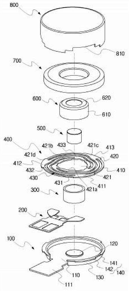
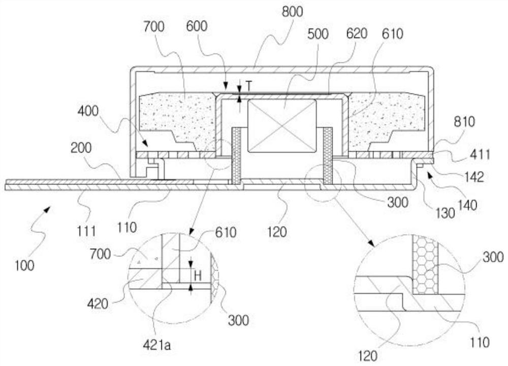
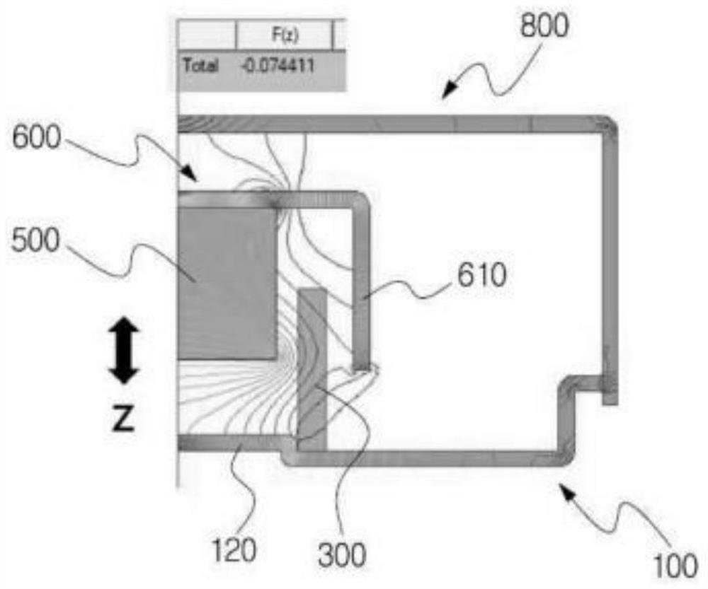
The present invention relates to a linear vibration motor comprising: a bracket, a coil, and a spring which are mounted on the bracket and connected to a weight part to amplify vibration and determinea resonance frequency; a magnet, the lower end of which is inserted into the upper part of the coil at a predetermined distance so that the upper end is fixed to the inner side surface of the upper part of the yoke part, generates a magnetic field by means of a permanent magnet, and generates up-down vibration by acting on the magnetic field of the coil; a yoke portion fixed to form a magnetic field closed loop, the yoke portion having a weight portion fixed to an outer side so as to concentrate a magnetic field; a weight part which is connected to the spring, amplifies the vibration by weight, determines a resonance frequency, and fixes the yoke part; and a box part which forms a housing to protect the vibrating body so as to form a magnetic field closed loop. Thus, eccentricity of the vibrating body can be prevented, intermediate assemblability can be improved, electromagnetic field force can be improved, and driving can be performed at a high response speed and a wide frequency band.
Description
technical field [0001] The present invention relates to a linear vibration motor, in particular to a linear vibration motor that fixes a coil at the center of a support to prevent eccentricity, improve intermediate assembly, and improve electromagnetic field force to improve vibration characteristics. Background technique [0002] Generally, with the recent rapid development of wireless communication technology, portable communication equipment is gradually developing towards miniaturization and light weight. With this trend of miniaturization and lightweight development, including The components of mechanical devices, IC chips and circuits have become highly concentrated and highly functional, so in order to improve space utilization, it is necessary to improve the size and shape. [0003] Furthermore, a large amount of research has been carried out on a flat vibration motor that is installed in a portable communication device and notifies the arrival of information through...
Claims
Login to View More Application Information
Patent Timeline
 Patent Type & Authority Applications(China)
IPC IPC(8): H02K33/02H02K1/34H02K7/04
CPCH02K33/02H02K1/34H02K7/04H02K33/16H02K5/24F16F1/027H04M19/047H02K2211/03
Inventor 姜振善崔教锡朴贤浚金华植李宗基
Owner 天津富禄通信技术有限公司
Features
- R&D
- Intellectual Property
- Life Sciences
- Materials
- Tech Scout
- Unparalleled Data Quality
- Higher Quality Content
- 60% Fewer Hallucinations
Learn More Browse by: Latest US Patents, China's latest patents, Technical Efficacy Thesaurus, Application Domain, Technology Topic, Popular Technical Reports.
© 2025 PatSnap. All rights reserved.Legal|Privacy policy|Modern Slavery Act Transparency Statement|Sitemap|About US| Contact US: help@patsnap.com


