Cylinder, in particular for a motor vehicle hydraulic brake system

A technology of hydraulic braking and motor vehicles, which is applied in the direction of mechanical equipment, engine components, engine sealing, etc., to achieve the effect of improving flow

Active Publication Date: 2008-12-17
CONTINENTAL AUTOMOTIVE TECH GMBH
View PDF10 Cites 2 Cited by
  • Summary
  • Abstract
  • Description
  • Claims
  • Application Information

AI Technical Summary

Problems solved by technology

In this application, the disadvantage is that the sealing ring with the ring back can be suction-fixed against the side wall of the annular groove

Method used


Image

  • Cylinder, in particular for a motor vehicle hydraulic brake system
  • Cylinder, in particular for a motor vehicle hydraulic brake system

Examples


Embodiment Construction

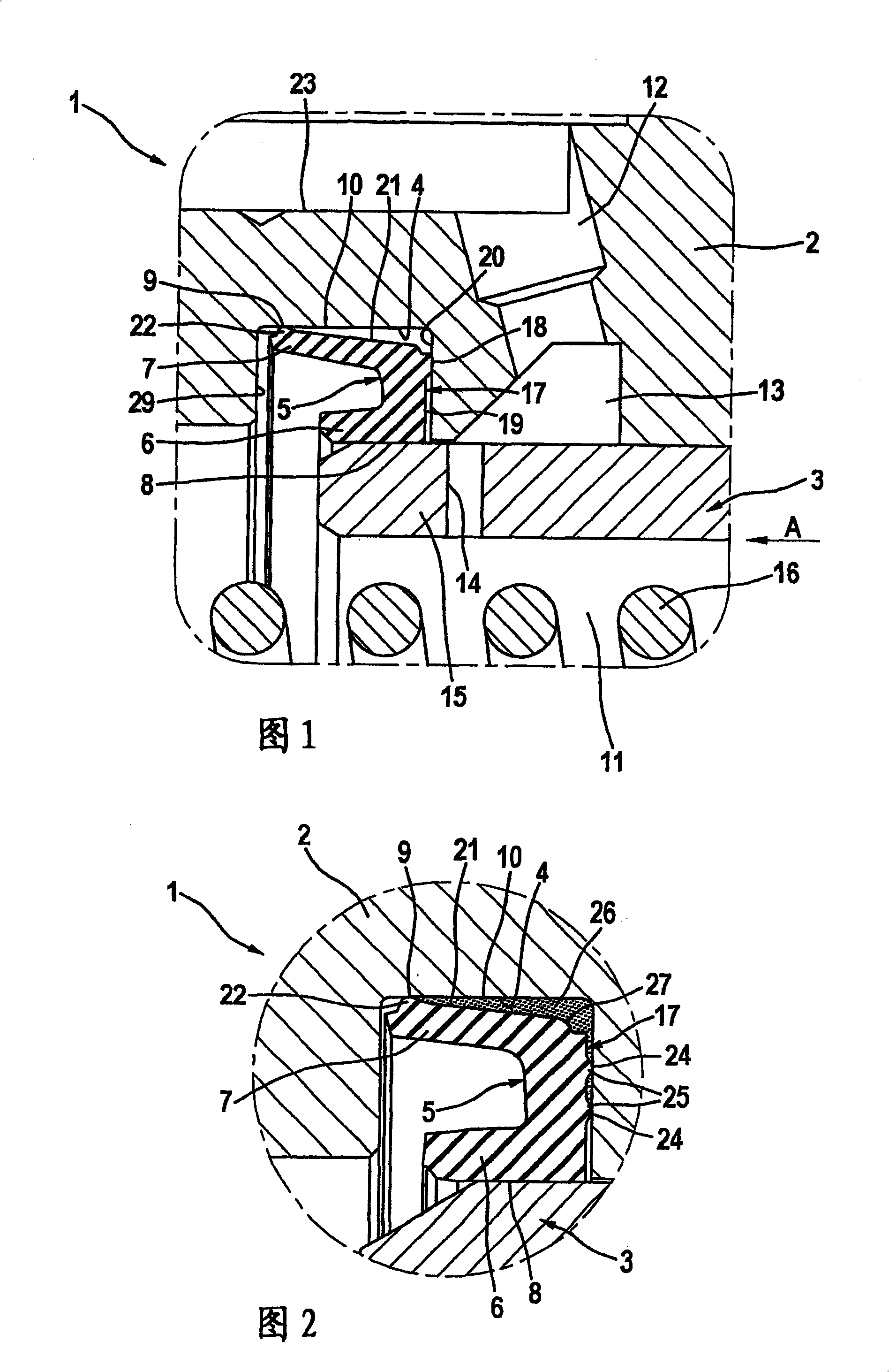
[0016] FIG. 1 shows in a partial view the components essential to the invention of a first embodiment of a cylinder designed, for example, in the form of a plunger and tandem construction for a hydraulic brake system of a motor vehicle. master cylinder 1. The way in which such a master cylinder 1 works is known in principle, so that the features essential to the invention will mainly be described. In addition, the two sequentially arranged pressure circuits of the master cylinder 1 in a tandem configuration are almost identical in structure and mode of operation, so only one pressure circuit will be described.

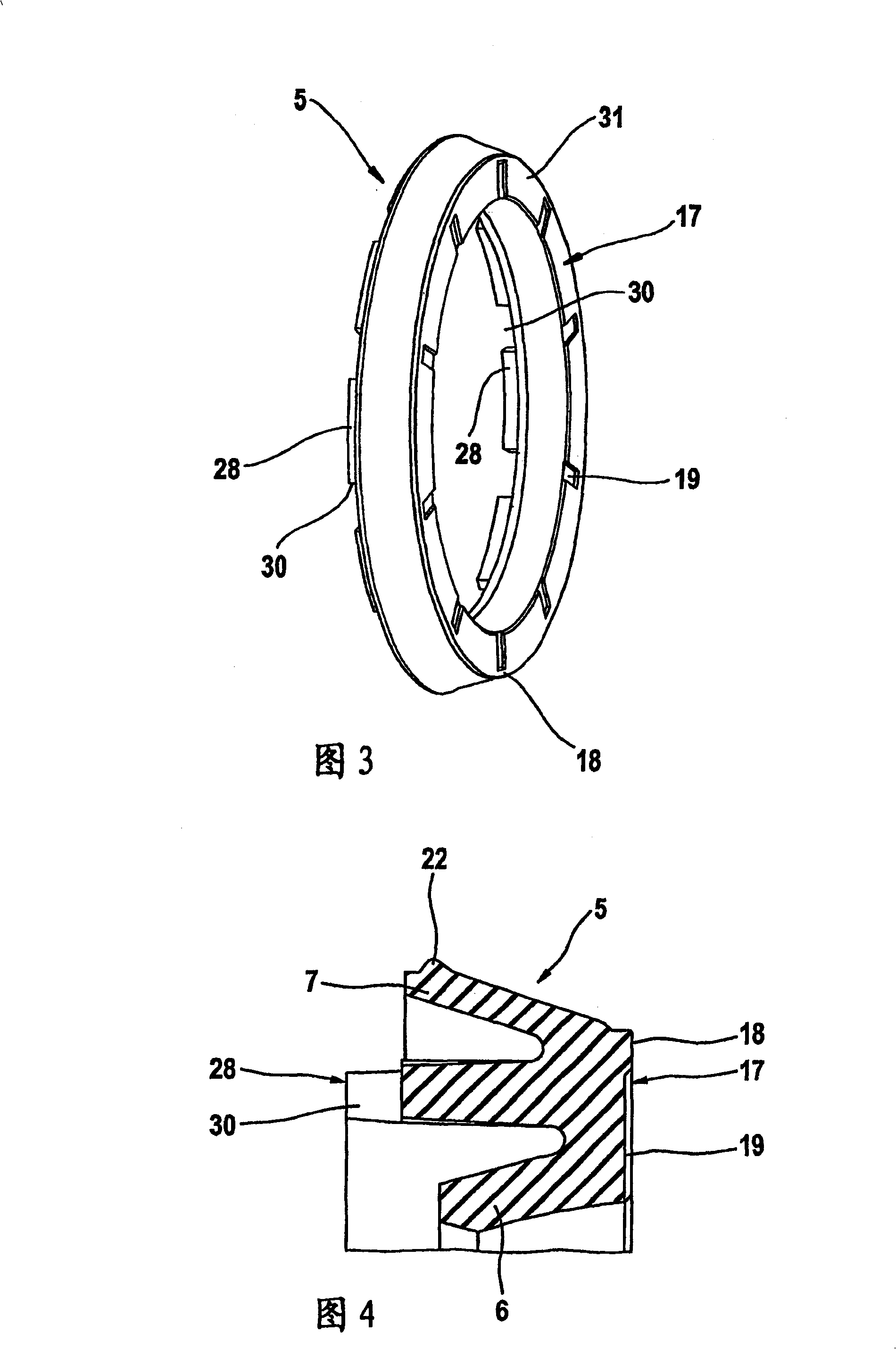
[0017] The pressure circuit of the master cylinder 1 shown in partial view comprises a plunger 3 which is movable in a housing 2, wherein an annular sealing ring 5 is arranged in an annular groove 4 of the housing 2 and has a dynamically stressed interior Sealing lip 6 and statically stressed outer sealing lip 7. The dynamically stressed inner sealing lip 6 bears aga...


PUM


Abstract

The invention relates to a cylinder, in particular for a motor vehicle hydraulic brake systems comprising at least one case (2) provided with a plunger piston (3) movable therein, at least one angular sealing collar (5) arranged in the snap ring groove (4) of the case (2), an internal lip (6) dynamically applied to the plunger piston (3) by a first sealing surface (8), an external lip (7) statically applied to the bottom of the snap ring groove (4) by a second sealing surface (9) and the back of the collar (17). Said invention is characterised in that the back of the collar (17) is not flat and is provided with at least one peripheral-sealing surface (18, 24).

Description

technical field [0001] The invention relates to a motor vehicle hydraulic brake system with driving dynamics control, comprising a master cylinder with at least one plunger movable in a housing and defining a pressure chamber connectable to a wheel brake ; At least one annular sealing ring, which is arranged in an annular groove of the housing and has a dynamically stressed inner sealing lip which rests against the plunger with a first sealing surface, and with a second sealing surface The statically stressed outer sealing lip and the ring back rest against the bottom of the annular groove, wherein a pump supplies pressure medium via the pressure chamber from a compensating container in the direction of the wheel brakes when the driving dynamics control is active, and The pressure medium flows through the outer sealing lip. Background technique [0002] A cylinder of this type is known from DE 101 20 913 A1. The cylinder comprises a sealing ring with a dynamically stressed...

Claims


Application Information

Patent Timeline
Patent Type & Authority Patents(China)
IPC IPC(8): B60T11/236F16J15/16
Inventor P·德洛特H·柯尼希U·容曼A·比朔夫
Owner CONTINENTAL AUTOMOTIVE TECH GMBH
Why Eureka
Try Eureka