Pneumatic diaphragm valve intelligent control system and method based on Internet of Things

An intelligent control system, pneumatic diaphragm valve technology, applied in the direction of diaphragm valve, diaphragm, valve details, etc., can solve the problems of short service life, small flow, and inability to remind parts replacement in time of pneumatic diaphragm valve, so as to prolong the service life and facilitate the Replacement, the effect of keeping the tightness stable

Active Publication Date: 2021-12-07
南京道隆生物科技有限公司
View PDF6 Cites 0 Cited by
  • Summary
  • Abstract
  • Description
  • Claims
  • Application Information

AI Technical Summary

Problems solved by technology

[0005] In order to overcome the shortcomings of the existing pneumatic diaphragm valves, the circulation is small, the service life of the pneumatic diaphragm valve is short under high-frequency conditions, and the airtightness of the equipment gradually deteriorates with the use of the pneumatic diaphragm valve, and the existing pneumatic diaphragm valve cannot promptly remind the shortcomings of parts replacement , technical problem: To provide a pneumatic diaphragm valve intelligent control system and method based on the Internet of Things, which has large flow rate, long service life, relatively stable sealing performance and easy replacement of parts in advance

Method used


Image

  • Pneumatic diaphragm valve intelligent control system and method based on Internet of Things
  • Pneumatic diaphragm valve intelligent control system and method based on Internet of Things
  • Pneumatic diaphragm valve intelligent control system and method based on Internet of Things

Examples


Embodiment Construction

[0035] The present invention will be further described below in conjunction with the accompanying drawings and specific embodiments.

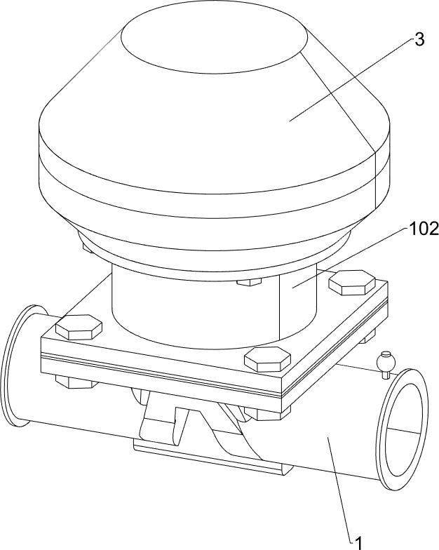
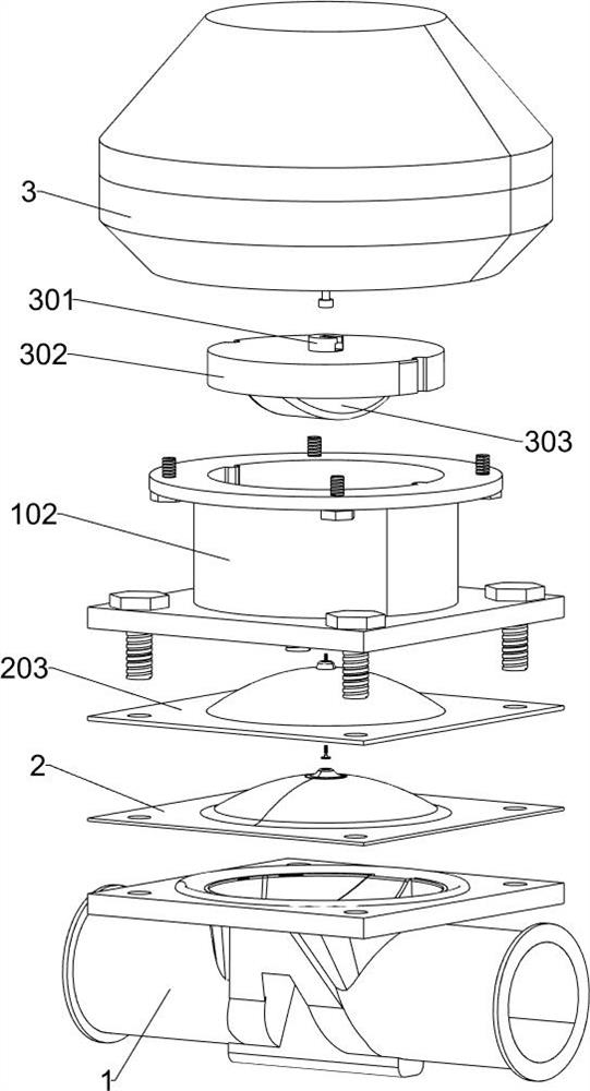
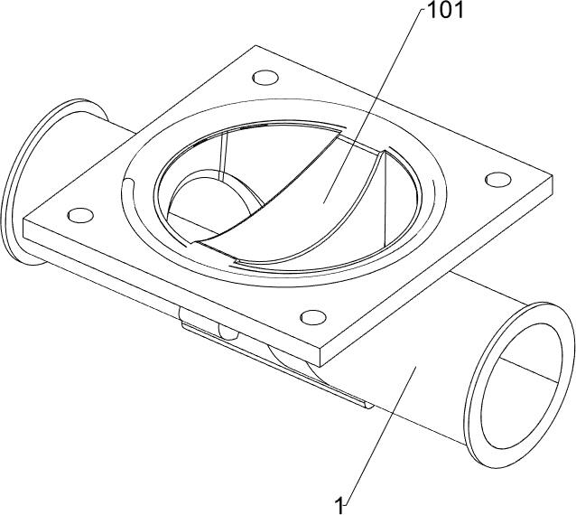
[0036] like Figure 1-Figure 3As shown, a pneumatic diaphragm valve intelligent control system based on the Internet of Things includes a valve body 1, a valve cover 102, a diaphragm assembly and a power assembly. The valve body 1 is connected to the valve cover 102 by bolts. A flow sensor is provided, a flow module is arranged on the flow sensor, the flow sensor is electrically connected to the flow module, the diaphragm assembly is arranged between the valve body 1 and the valve cover 102, and a pressure sensor is arranged on the diaphragm assembly, the pressure sensor There is a pressure module on the top, the pressure sensor is electrically connected with the pressure module, and the inner wall of the valve cover 102 is provided with two vertical convex rails. A two-way solenoid valve is provided, and a control module is arranged on the tw...


PUM


Abstract

The invention relates to the field of diaphragm valve intelligent control, in particular to a pneumatic diaphragm valve intelligent control system and method based on the Internet of Things. The pneumatic diaphragm valve intelligent control system based on the internet of things is large in circulation amount, long in service life, relatively stable in sealing retentivity and convenient for replacing parts in advance. A pneumatic diaphragm valve intelligent control system based on the internet of things comprises a valve body, a valve cover and a diaphragm assembly, wherein the valve body is in bolted connection with the valve cover, a flow sensor is arranged at the fluid outflow end of the valve body, a flow module is arranged on the flow sensor, the flow sensor is electrically connected with the flow module, and the diaphragm assembly is arranged between the valve body and the valve cover. The flow cross section of fluid is increased through the design of the arc-shaped groove in the valve body, the adhesive force between the valve body and the diaphragm is increased and the service life of the valve body is prolonged through the design of the connecting piece, so that problems generated during fluid filling are displayed through the field control panel, and the service lives of parts are reminded.

Description

technical field [0001] The invention relates to the field of intelligent control of diaphragm valves, in particular to an intelligent control system and method for a pneumatic diaphragm valve based on the Internet of Things. Background technique [0002] In the process of conveying the medium, the pneumatic diaphragm valve controls the conveying effect of the medium. The operating conditions of the pneumatic diaphragm valve are complicated. In some high-frequency working environments, the pneumatic diaphragm valve is easily damaged, and the pneumatic diaphragm valve is used with The blocking effect of itself becomes worse, which affects the effectiveness of work. [0003] The distance between the diaphragm and the valve body of the existing pneumatic diaphragm valve is small, so that the flow cross section of the medium becomes smaller, and the flow rate of the medium after flowing through the pneumatic diaphragm valve becomes smaller, which affects the delivery efficiency o...

Claims


Application Information

Patent Timeline
IPC IPC(8): F16K7/14F16K37/00F16K31/122F16K27/02
CPCF16K7/126F16K7/14F16K37/0091F16K31/122F16K27/0236
Inventor 刘波
Owner 南京道隆生物科技有限公司
Why Eureka
Try Eureka